This test is a long time coming. A couple years ago at CLA, Steve Chapman and I were looking over a flint gun made by Allan Sandy. The vent Allan used had two smaller holes located horizontally. Allan said the vent was internally coned but used two .052″ holes. Allan said he didn’t know whether it was faster or slower than a normal vent. My reply was that I could time it. Allan offered to provide me a vent, and on the way home, Steve and I planned how the vent would be tested.
Time passed with many interruptions in the way. In the meantime Fred Stutzenberger entered the picture. I believe Fred saw the “double-hole vent” on Sandy’s table at the same show that we did. Fred however, was more prompt than we were and published an article on the vent in the August 2014 issue of MuzzleBlasts.
Without great detail, Fred’s article compared Allan’s double-hole vent with a single-hole vent that had the same area as the sum of the two smaller vents. His findings showed that shots fired with the double-hole vent had slightly higher velocities than the single-hole vent even, though the vent area was the same. The “choked-flow principle” (comparing circumference to area) is the likely cause. Fred explains this better than I do; please read the article.
Our testing focused only on ignition speeds. We compared ignition time of the double-hole vent (two .052″ holes) and the single-hole vent (.073″) Both vents have the same area, but vary in their circumferences.
The main question I have is, “If the choked flow principle tends to restrict flow leaving the vent, might it also restrict flow entering the vent, causing slower ignition?”
We used a 10″ barrel stub with a small Siler flint. The test used a double-hole vent with .052 holes and a single-hole vent with a .073 hole. We did 10 trials each and lit the pan with a red hot copper wire. Our reason for this was to prevent a changing flint edge from entering into the test. The single .073 vent was better both in speed and consistency.
Before finishing, we ran 5 trials each in which the pan was ignited by the small Siler. In those trials the single-hole vent was better, but by a smaller margin. None of the trials sounded abnormal to the ear. No matter the range from high to low, human senses could not tell the difference. In fact, Steve tried to guess and was invariably wrong.
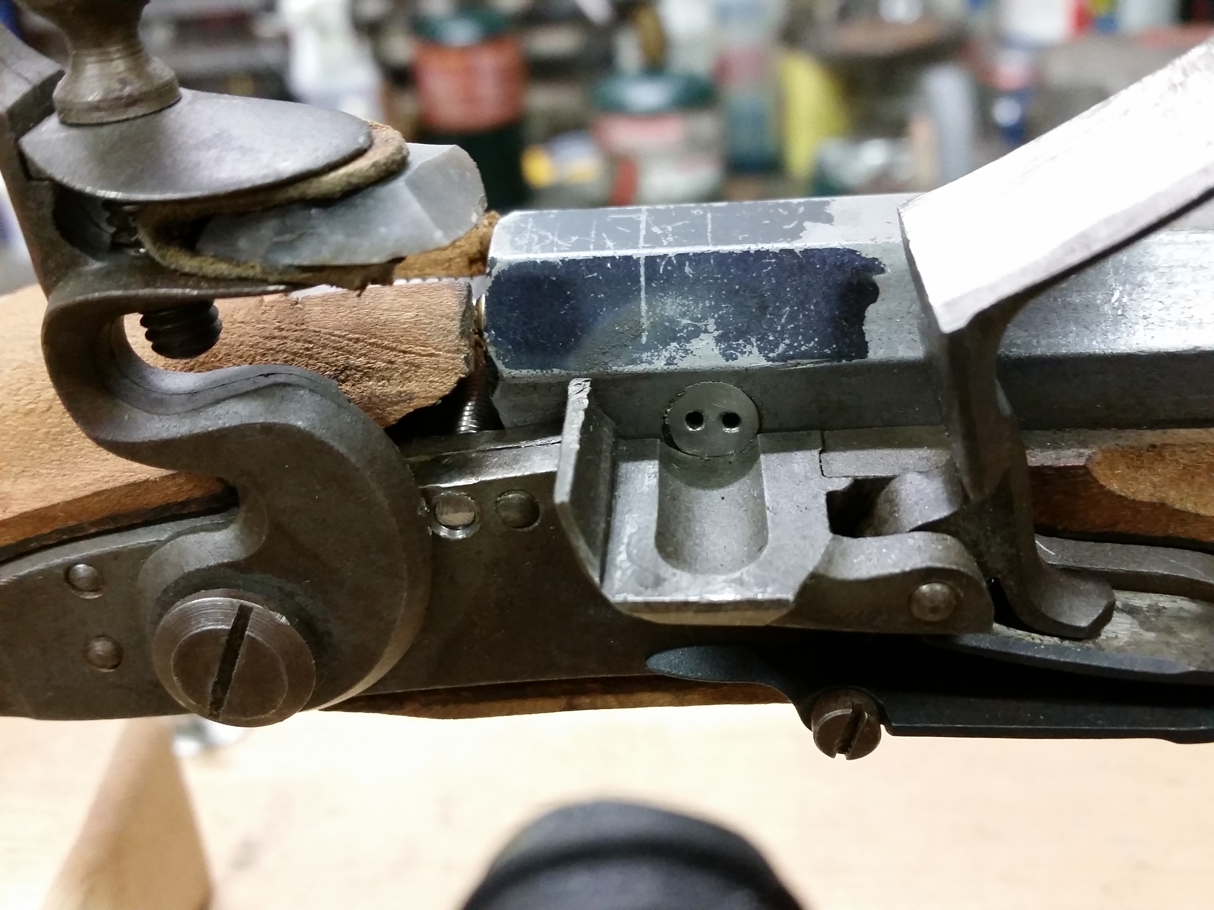
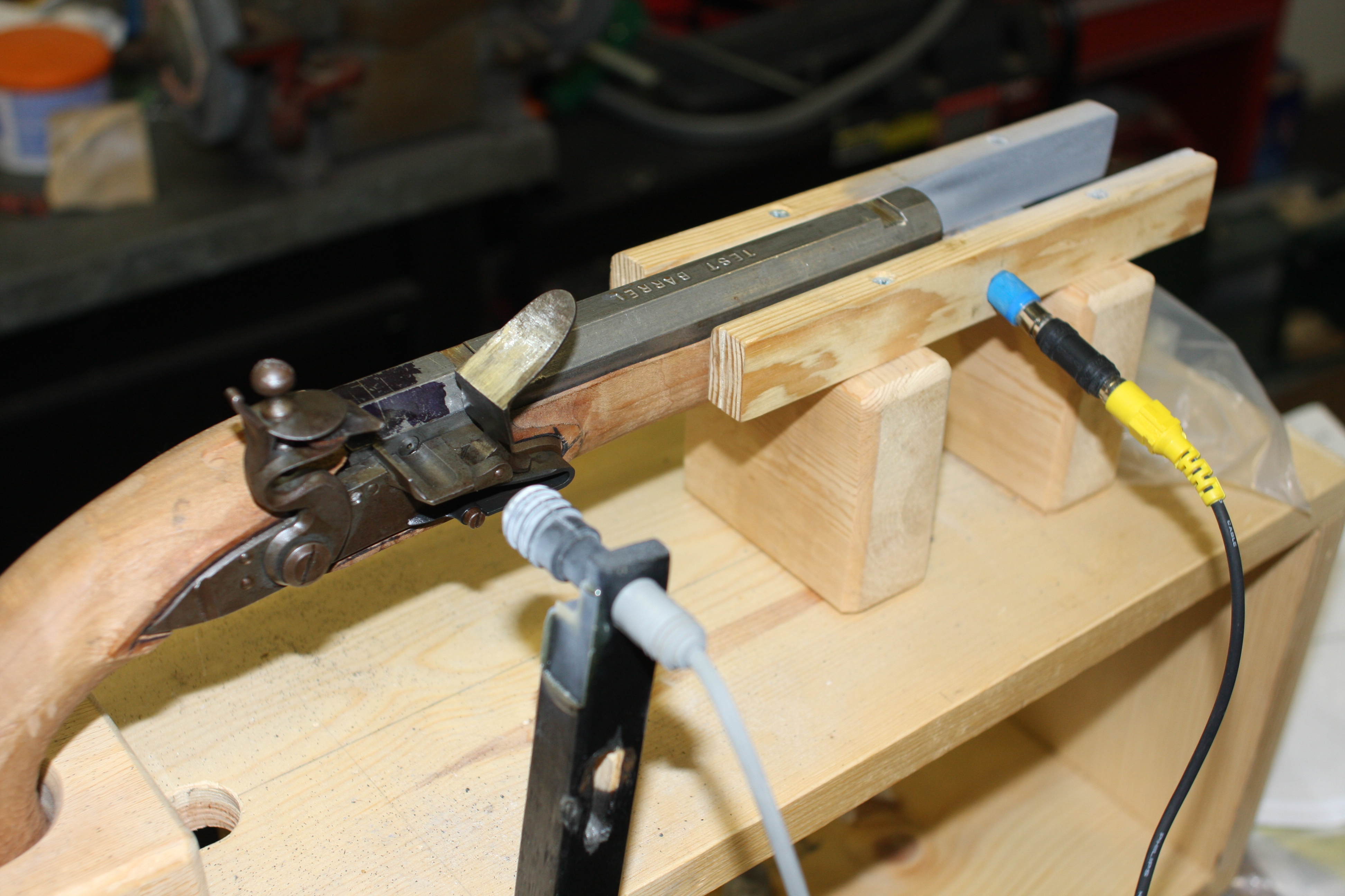
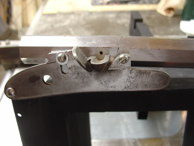
Here you see the shield that prevented both photocells from triggering when the pan flashed
Interpreting the results can sometimes be misleading. In this case, I like the single-hole vent. However, I do have two doubts. (1) I have questions about the reliability of a vent as small as .052”. A double-hole vent with larger holes might alter the result. (2) I wonder if the shape of vent’s exterior would change the result.
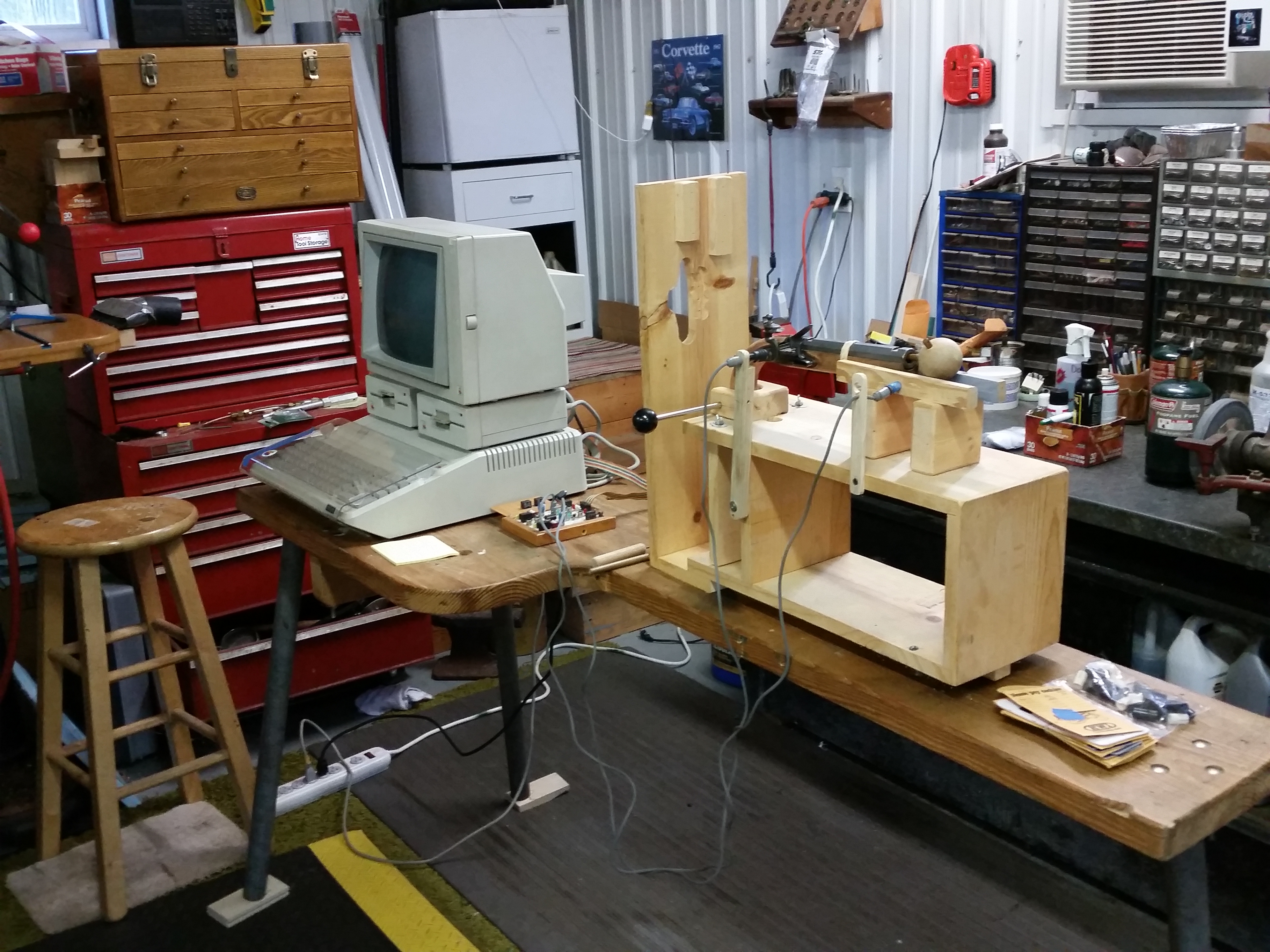
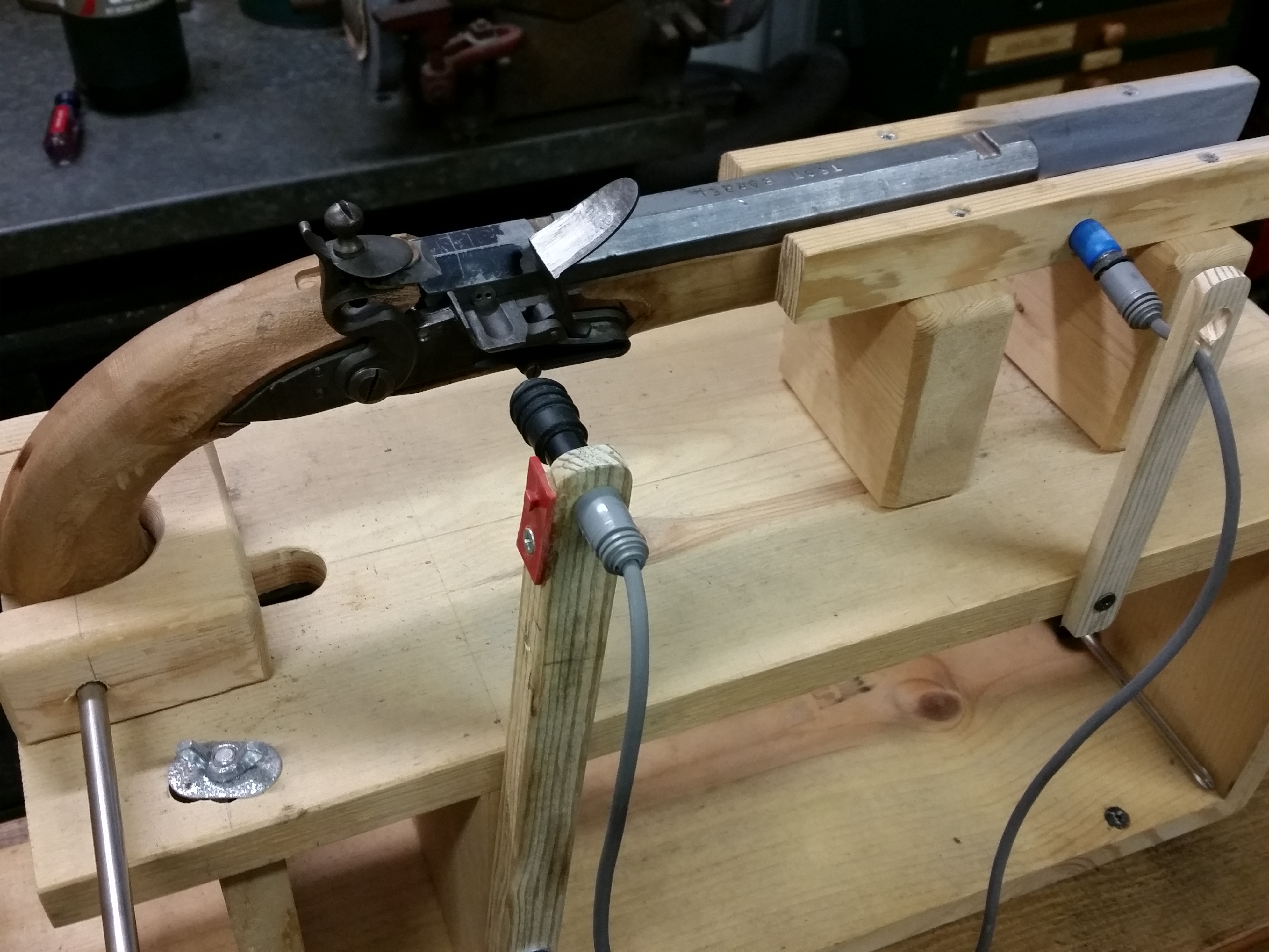
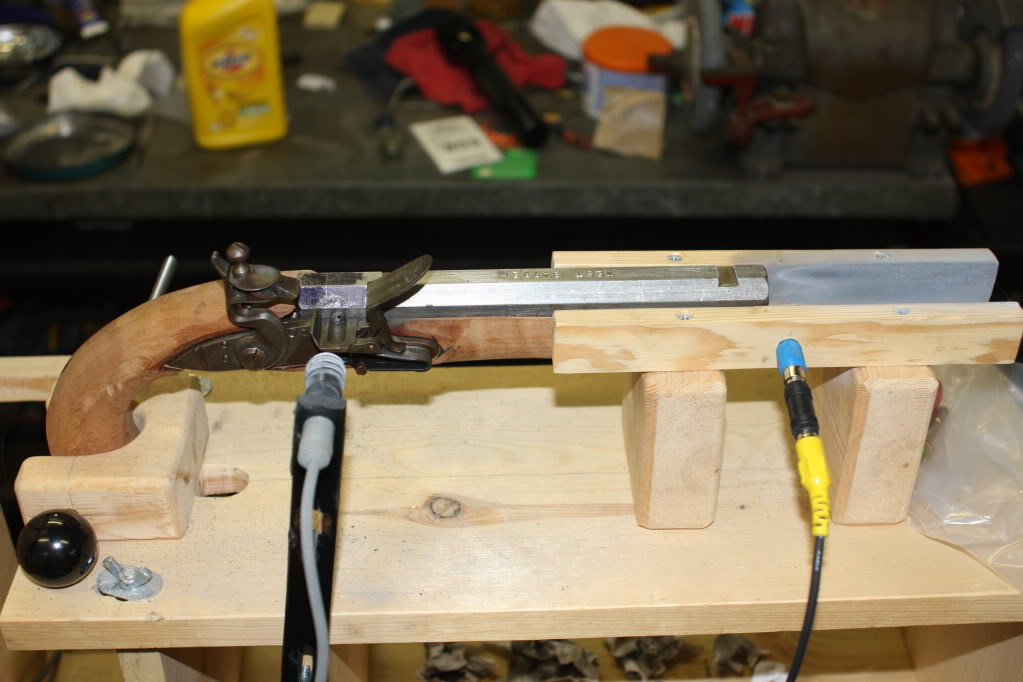
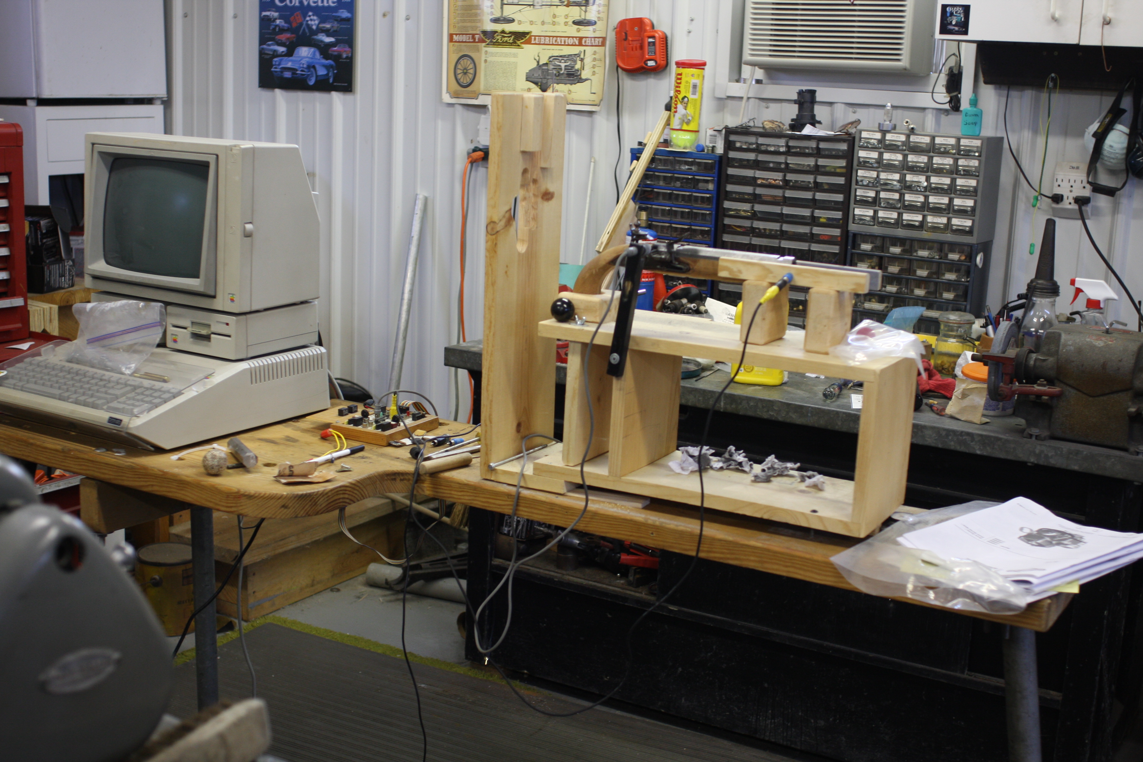
The included photos show the fixture and the position of the photo cells used in the timing. The photo cell at the pan trigger the start, while the photo cell and the muzzle triggers the stop.
The last pic is a close up of the vent. These holes are .052″. BTW, the stock is a heavily mutilated factory second supplied by Jim Chambers. It was important because it allowed the sear to be struck from below by the plunger. It also allowed us to use a small Siler lock for an earlier test. At that time it allowed three different locks to be tested using the same lock mortice.
To conclude, I’d like to thank Allan Sandy for the chance to time his vent. I feel that this vent type is well worth studying. I’d like to repeat this with a .055” 2 hole vent.
My thanks also to Steve Chapman and Mike Coggeshall for their assistance in the testing.
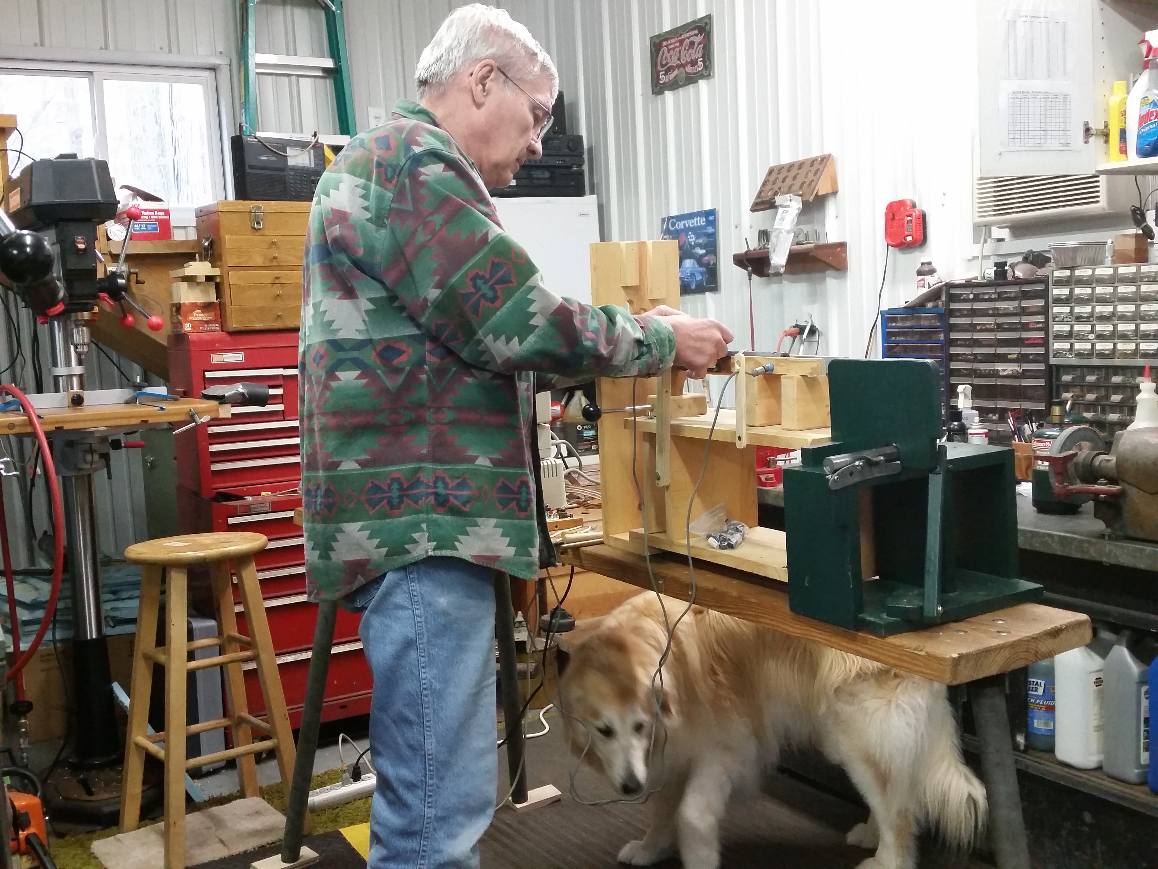
Of course every experimenter needs a furry assistant
Filling a flintlock touch hole with priming powder causes a slower ignition. The pan fire has to burn through instead of flash through the vent. Is this “fuse effect” true? Can the difference be measured? Are the “hang fires” experienced by black powder shooters caused by something else? Reporting the answers to these questions is the purpose in this article.
The purpose of this test was to see if there was a measurable delay in ignition when a straight cylinder vent was filled with priming powder. (We did not deal with vent liners in this test.) For the purpose of this experiment I will define this “fuse effect” as an ignition delay caused by the priming powder having to burn its way through the vent to ignite the main charge instead of “flashing” through the vent. I’m personally not fond of the term because it implies that we know what caused the delay. I like the term “hang fire” because it does not suggest a cause.
The test was set up using a fixture we used earlier to time lock ignition speeds. We used a “pistol” with a barrel stub, small Siler lock, and my computer with photo cells “looking” at the pan and barrel muzzle. The barrel is loaded with 30 gr 3fg and a sabot to hold powder in place. The pan is primed, and ignited with a red hot wire to eliminate lock variables. Between firings, the barrel is wiped with two patches, a vent pick used, and compressed air is blown through the vent to insure that the vent is clean. The pan is primed with Null B close to the barrel. The only difference between the two test phases was that the vent was completely empty in one, while in the other, we picked priming powder into the vent until no more would go in.
The barrel used was octagon 7/8” across the flats and was .45 caliber. It had a flat flint-type breech. The vent was a straight cylinder with a 1/16” diameter approximately .21 inches in length. Time starts when the pan photo cell is triggered and stops when the barrel photo cell is triggered. Thus barrel time is included in this test, however this obviously the same for both vent conditions.
We recorded 5 trials for each vent condition. The average time for the clean, empty vent was .028 seconds. The filled vent average was .031 seconds. As you would expect, the slowest time we recorded was in the filled vent phase (.0363). However the fastest time of the day was also in the filled vent phase (.0233). (We also did a single clean vent trial where we banked the prime away from the vent and recorded at time of .067 – more than two times slower than the clean vent average.)
These averages are quite close together. We expected a larger difference because our ears tell us a hang fire has taken place. And, here is the most unusual finding. The fastest time (.0233) we recorded sounded as if it was a hang fire. The slowest time (.0363) recorded sounded like a sharp crack – no hang fire – sounded like a .22 rim fire. This reinforces a belief I have long held that our eyes and ears are terrible tools for judging flint events.
This all makes me wonder what we are really hearing. Maybe our ears send us false information. Consider this: You are three shots into a target and have 3 tens. You shoot the 4th shot and it’s a nine. Sounded fast, but you think it was just you. You shoot the 5th shot, and it has an audible hang. You look through the scope, and no. 5 is back in the 10 ring. Maybe the fourth shot was slow, the fifth shot was fast, and your ears are at fault. With what we learned here, it could be possible. I truly don’t know the answer. Sometimes experiments leave you with more questions than answers. I do know that I trust my ears less than the numbers.
There are so many variables that can cause delays that in most cases it can be impossible to rule out all but one. That was the purpose in our experiment. We wanted to put a number on the amount of delay, if any, caused by packing a cylinder vent with priming powder.
The delays we found were measurable but not large enough to account for the delays we have measured in pan ignition – where the variables were flint edges, priming, particle size, and location of the prime in the pan. I have measured far larger time variations caused by these variations. The other big factor is the delay caused by fouling in the vent. A vent full of priming is one thing, but a vent filled with fouling is quite another. Besides causing huge hang fires, I believe fouled vents are the flint shooter’s biggest cause of failures to fire.
If I were to list the top causes for delays based on my testing they would be:
1. Lack of good spark production from good flint edge
2. Improper priming location in the pan with good priming powder
3. Vent not absolutely clear of fouling.
(A clean vent filled with prime is not a major cause IMHO.)
[box type=”note” align=”aligncenter” ]Reprinted from MuzzleBlasts April 2005 by Larry Pletcher —- This article is another in a series of reprinted articles that measure a flintlock’s ability to ignite black powder. This article compares ignition time of black powder varieties used for priming the flintlock pan.[/box]
As a retired educator and a student of the flintlock, I am fascinated with what we can learn by applying technology to the field of black powder. This is another in a series of articles that uses a computer interface to experiment with our black powder hobby. The first articles (1990-1992) described experiments timing various flintlocks. Another article (2000) described the timing of touch holes. This article explores the timing of different grades of black powder used for flintlock priming.
My initial goal was to compare priming powder. Two samples of Goex 4fg were included. The ’89 Goex sample came from the plant before the plant explosion and will be referred to as “Early Goex”. The second Goex sample, “Late Goex”, was produced after the plant was relocated.
Two Swiss samples were included as well. These were purchased at Friendship at the fall 2004 shoot. One sample is the normal Swiss 4fg priming powder. The other sample is called Null B. This powder is reputed to be the tailings (sweepings) left from production runs of the other grades of Swiss. Finishing the test group were Goex samples of 2fg and 3fg. Because 3fg and 2fg powder are at times used as priming powder, it seemed logical to include these grades of powder as well.
In experimentation of any kind, controlling variables is a very important responsibility. In tests involving a flintlock, this is especially difficult. In this experiment, the variable we wish to test is the powder, and it is important to control all remaining variables.
Humidity is one of the variables which I wished to control. Since I had no means to manipulate the humidity up or down, I took a number of steps to minimize its fluctuation. These tests were completed in an insulated garage used to store antique cars. An exhaust fan was used to remove the smoke. The day for the testing was chosen with humidity in mind. I noted humidity at the beginning and end of each powder test group. The humidity was 63% when I began testing, and dropped to 48% by the time testing was complete. I felt this range was acceptable and was probably the best I could do. Without the fan, the humidity might have been more uniform, but firing a flintlock 140 times in an enclosed garage would have obvious disadvantages. The physical equipment remained the same as the apparatus used in the earlier testing. It has remained unchanged for years, but more important, it was unchanged throughout all six powder tests. The software and lock also remained unchanged throughout all testing. The lock is a large Siler that has been a workhorse in my years of testing. The Siler has been a benchmark for my work and is the lock I have tested the most.
The variable that is the most difficult to control is the flint edge. In an ideal world the flint edge would be identical throughout all trials. In reality the edge is different on every trial. Every strike against the frizzen leaves a different edge because of the flint fragments that break off with each try. Flint shooters also recognize this problem and strive to manage it. During the testing, I took a number of steps to minimize this variable. Every powder test group was begun with a new flint. Every powder test group was begun with the lock removed and cleaned. The flint edge and frizzen were cleaned between each individual trial. The flint was knapped whenever the elapsed time or my experience made me feel it was necessary. The way powder is placed in the pan can also be a variable. However, in these tests the only concern is to provide a uniform powder area for sparks’ landing. The procedure used was to fill the pan level full. In this way, sparks from every trial have the identical bed of powder on which to land.
The fixture that holds the lock is largely unchanged for the last 10 years. The lock is mounted in the fixture locating the sear bar directly over a 12 volt solenoid. A photo cell is mounted so that it “looks” into the pan. Both the solenoid and the photo cell are attached to the computer, using a high school physics interface. The computer program controls the firing of the solenoid, sensing the photo cell, and measuring the time in between the two. After the lock is prepared for firing, pressing the space bar on the computer fires the lock and starts the machine language timing routine. When the pan flashes, the photo cell stops the timer which reads to the nearest ten thousandths of a second.
The times for 20 trials are recorded on a spreadsheet. The spreadsheet subtracts the time it takes for the solenoid to reach the sear. The remaining time begins as the sear is tripped and ends with pan ignition. The spreadsheet then finds the fast time, slow time, variation, average, and standard deviation. Beginning and ending humidity are noted. These stats are the basis for the article. The powders’ spreadsheets are included at the end of the article. Summary sheets and graphs were made for comparison.
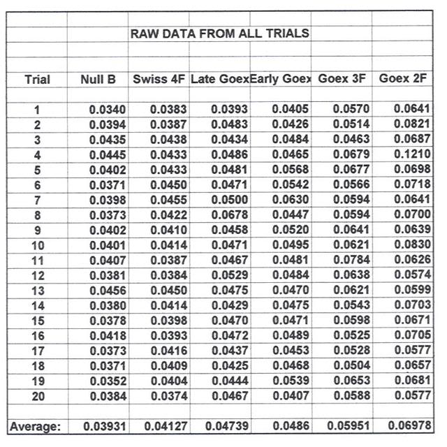
A summary of all the tests can be seen in the following Chart. In this chart you can see all trials for each powder in the order they were fired. Each powder’s average is shown at the bottom.
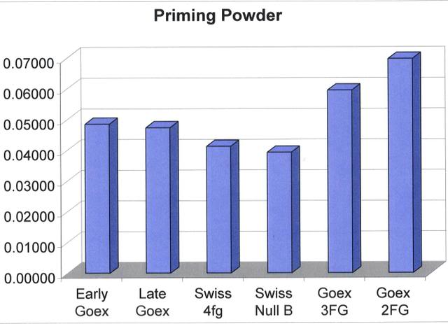
The next chart shows the averages for each group as a bar graph. One can see a gradual decrease in the times of the four priming powders. Then the times increase as the fffg and ffg powders are displayed. It is worth noting that the fastest powder (Null B) also had the finest granule, and the slowest powder (ffg) had the largest granule.
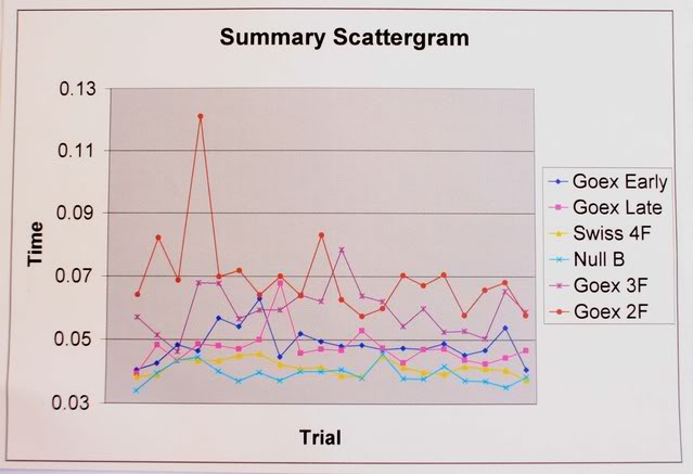
The aqua and yellow on the scattergram indicate the two Swiss powders. It should be obvious that these powders were the fastest and the most consistent of all the powders tested. The variations between fast and slow times were every small. From the experimenter’s standpoint, these powders look very good. They were so consistent that it was difficult to tell if or when the flints needed knapping. The Null B powder was marginally faster. However, any trial from one of these powders would fit nicely in the other. The slowest time in each was within .0001 of each other. Each powder has an advantage when one looks at the results closely. The Null B has the fastest average, and the Swiss 4fg has the smallest variation and standard deviation. In fact, the variation for the 4fg is astonishingly small at .0081 of a second. This very small variation gives it the edge in standard deviation also. (Standard deviation can be thought of as a measure of consistency. The more consistent the trials, the lower the standard deviation will be. Sixty-six percent of the trials should fall within one standard deviation of the average. Ninety-six percent fall within two standard deviations.)
The red and blue represent Goex ffffg priming powder before and after their factory accident. These powders compare well together. A quick summary would be to say that the early Goex was slightly more consistent, and the late Goex was slightly faster. Both of these powders are slightly slower than the Swiss powders. About three quarters of the Goex times fall outside of the high to low interval on the Swiss chart.
The colors violet and brown represent the Goex 3fg and 2fg powder. While these powders are not considered priming powder, both are used as prime especially in military applications where paper cartridges are used. While it is apparent that these powders are slower than the various priming powders, one also notices that they are much less consistent than the rest. The variation between fast and slow times was considerably larger.
In comparing the 2fg and 3fg powders to each other, one can see that while the fffg Goex powder averaged faster than the 2fg Goex, it also had a big advantage in consistency. The 2fg powder had a particularly large variation due mainly to a very slow ignition in one trial. This trial seems uncharacteristic based upon the rest of the times, but is reported in the interest of accuracy. Knapping the flint produced a faster subsequent trial. The question, “Why didn’t I knap the flint one shot sooner?” is a problem for the experimenter as well as the flintlock shooter.
When making comparisons between these powders and the priming powders, one can see that the true priming powders hold a substantial advantage. For instance, the fastest 3fg time is slower than the slowest of the Swiss times. Variations from high to low are greater as well. Drawing conclusions after the experimentation requires great care. One conclusion deals with the comparison of priming and non-priming powder. While there was a significant difference, I could not discern this difference with human senses. Friends, who report that their ignition with regular horn powder is just as fast, support this. Their ignition is slower, I believe, but we cannot detect the difference without scientific means.
The results from timing the four priming powder samples were even closer. While this experiment can measure differences in the ignition speeds of these samples, the human eye and ear cannot tell the difference. The variations between the priming powders tested here are simply too small for human senses to detect. That said, one piece of anecdotal information was gathered this fall at Friendship. A good friend who is a rifle and horn builder from Duck River, TN, told me that he thought the new Null B powder was extremely consistent shot to shot. He is not wrong.
At the end of my first article in 1990, I wrote, “This article just scratches the surface.” I feel the same way today. There are many things about the way black powder ignites which need more study. As an example, the humidity range that shooters encounter is far wider than the relatively narrow humidity range in this experiment. If this experiment would be repeated at either humidity extreme, the results may give us more insight about these powder samples. I am interested in any study methods that help add to our knowledge. Readers with ideas may reach me at 4595 E. Woodland Acres, Syracuse, IN 46567.
Comparing the strength of the black powder burn by looking through the barrel muzzle. Here we see that where the black powder is placed in a flintlock pan is crucial.
In this phase I used a digital camera to photograph the fire coming through the vent. The barrel is mounted on a fixture and the camera installed on the tripod. Height was adjusted until the camera looked directly into the muzzle. In this position the barrel in centered in the camera and the pan is to the left. On the right side of the barrel directly opposite the vent is a cleanout hole. (The cleanout is important as you view the photos.)
The pan was primed with .5 grain of Swiss Null B priming powder in three pan positions: banked to the outside, close to the vent, and as close as possible without blocking the vent. The pan powder was carefully positioned using a pencil with a round eraser. Since the eraser was the same shape as the pan bottom, this worked very well.
The camera was set to have the shutter open for 4 seconds. Once the pan was primed, the procedure was to fire the camera and then ignite the pan. The pan was ignited as earlier with a red hot copper wire. (There is NO barrel powder used until the last phase.)
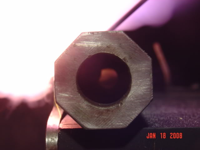
Photo 1 shows the muzzle shot taken with .5 gr of Swiss Null B priming powder banked away from the vent.
Photo 2 shows the muzzle shot taken with .5 gr of Swiss Null B priming powder positioned close to the vent.
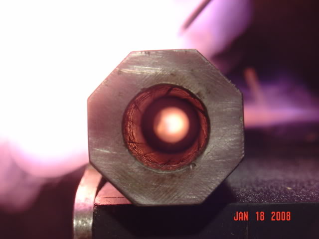
Photo 3 shows the muzzle shot taken with .5 gr of Swiss Null B priming powder positioned as close to the vent as possible without covering it.
Examination of the photos add evidence for stronger ignition with closer placement of the pan powder. Comparing the photos showing the close position and the “banked away” position shows a clearly stronger fire in the barrel and also traveling through the cleanout hole on the far side. While evidence continues to support a close priming of the pan, only timing of the positions will provide conclusive proof. That comes next.
Determining the amount of black powder to be used in testing. Since flintlock pans are of different size, I felt that this was a necessary step in our process.
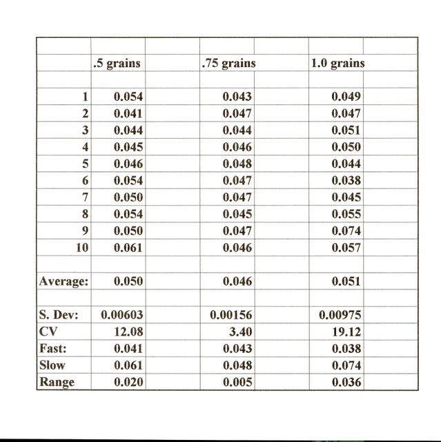
In this phase of testing I timed different amounts of priming powder. Ten amounts each of .5 grains, .75 grains, and 1.0 grains of Swiss Null B priming powder were weighed to the nearest tenth of a grain. These were timed in the fixture to see if varying the amount of prime affects the speed or consistency.
The fixture allowed the barrel to be rotated to vertical to load 15 grains of Swiss fffg for the barrel powder. The barrel was then rotated to level and the pan primed. Photo cells were checked to make sure they are pointed at the pan and the muzzle. The last step was to make sure the computer was ready. The pan was ignited with a hot copper wire and the readings recorded. The barrel was wiped between trials.
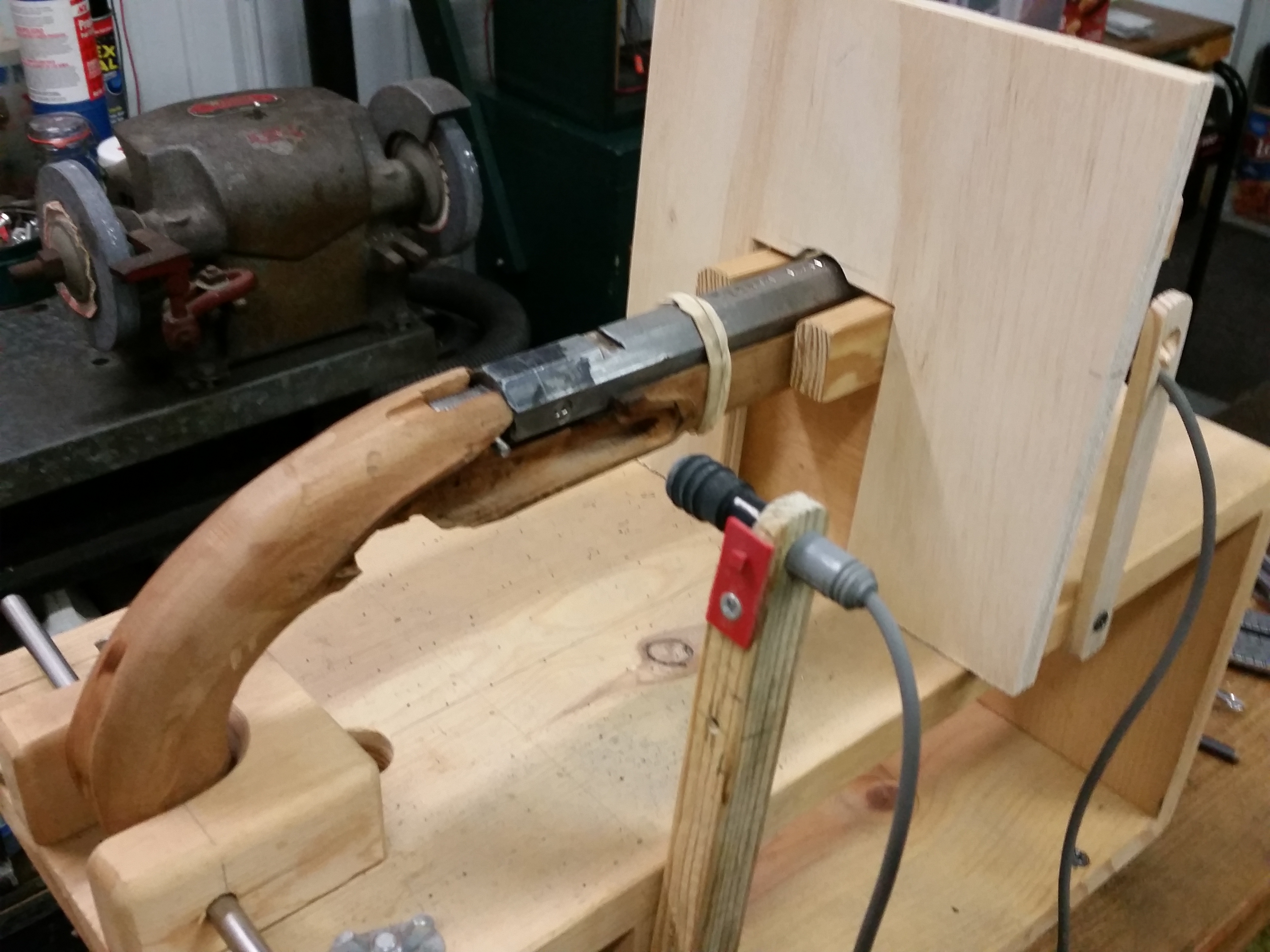
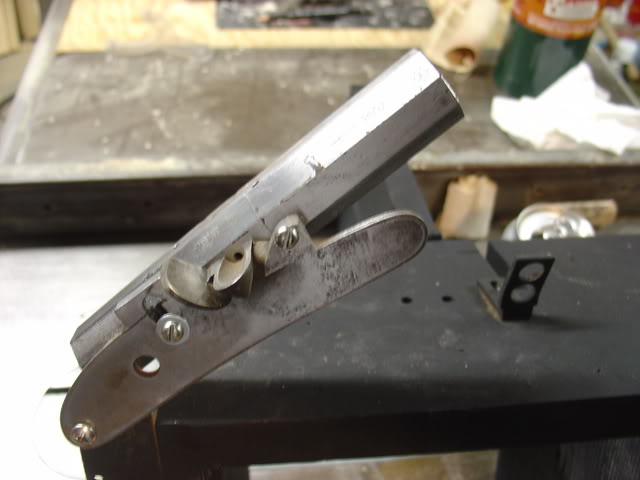
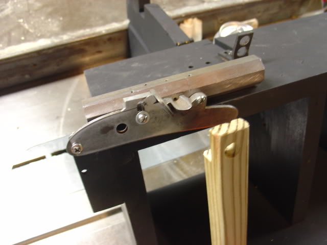
Photos of the fixture are shown below.
These two fixture photos also show the range of movement that can be used to test the location of the vent hole in relation to the pan. The top photo shows the hole in it’s lowest location, while the bottom photo shows highest location. For all tests so far, the vent hole has been centered on a line level with the top of the pan.
The graph below shows the trials with the three different priming powder amounts:
In evaluating the results of this test, I found Joe Sharber to be of great help. Joe, a fellow blackpowder fan with statistical experience, provided help with the number crunching. He pointed out that there is no statistically significant difference in the average ignition times. However he also noted that the variability or standard deviation was statistically significant.
Joe suggested that the term “Coefficient of Variation” * may be of value as a measure of consistency. The CV listed in the chart helps to show the advantage in consistency of the trials done with .75 grain priming powder. Because of this .75 grain will be the powder amount used in future tests.
* Coeficient of Variation is defined as 100 x (standard deviation divided by the mean). It is given as a percent. My thanks to Mr. Sharber for his assistance.
Is it better to bank the black powder priming away from the vent? This piece of conventional flintlock wisdom will be tested.
Part 5 of our test series will examine the question about where in the pan provides the best ignition. Conventional wisdom has told us that banking the priming powder away from the vent will produce the fastest ignition. Practically avery black powder shooter has heard this. This theory is based on human senses or what looks and sounds fast. The current test is designed to see if conventional wisdom is correct.
Early attempts showed a trend developing but had results that did not fit the rest of the range. A careful plan was developed to remove as many variables as possible especially those that were caused by fouling. Between firings the following were done:
The barrel was wiped. An additional step was added here and explained in the video.
A pan brush was used.
A pipe cleaner was used in the vent.
Compressed air was blown into the vent.
The priming powder used was Swiss Null B weighed on a balance scales. Since earlier testing showed its consistency, .75 gr was used. Because the placement of priming powder was the variable, care was used in its placement. The charge was poured into the pan and moved into the test positions using pencil with a rounded eraser. Powder could be pushed to the outer edge of the pan as well as very close to the vent. In both of these positions I felt that I was using more care in the powder placement than the normal firing of the lock in the gun. I realized that I chose the extremes in powder placement, and that a shooter would fall somewhere in between.
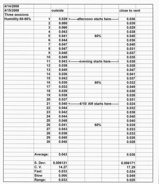
The tests were run in a 24 hour period with temperature controlled by thermostat. The day was picked with humidity in mind. The humidity varied within a range from 60 – 66 %. This is noted on the spreadsheets. Each battery of tests consisted of ten trials each – prime banked away from the vent, and prime placed as close to the vent as possible without covering it. To insure that no priming method had a unfair advantage, the trials were alternated so that a complete test battery included 10 trials each, alternated for a total of 20 trials.
At the end of the test session the ten trials for each priming method were recorded and all parts cleaned. Battery 1 was done in the afternoon at 60% humidity. Battery 2 was done in the evening at 66% humidity. The final battery was done the following morning at 60% humidity.
I made a short video that showed the processes involved:
The results are shown in the spreadsheet below.
The obvious conclusion is that banking the prime away from the vent doesn’t produce the most rapid ignition as we once thought. Banking the powder way from the vent actually reduced the ignition speed by 16%. This conclusion runs counter to conventional wisdom heard for years in muzzle loading circles. However, it is consistent with earlier tests where we saw photos with brighter fire from a close positioning of the prime.
While these results change the way I will prime my flintlock, there are other considerations that must be dealt with. In my tests the pan was ignited by a copper wire heated red hot. In the real flint world the sparks need a bed of powder on which to land, and this must be part of or priming procedure. This means that when I prime my locks, my emphasis will be close to the vent rather than away from it, but the bottom of the pan must have sufficient prime for sparks to land in. Thus, how well a lock places its sparks in the pan becomes an equally important consideration.
One other result of this experiment is that I have become increasingly skeptical of human senses in how I perceive flintlock ignition. And, there are more questions. What about low vent locations? This has always been rejected as a cause of slow ignition. Maybe we’re wrong about that as well. We’ll look at that in Part 6.
Low vs High Vent Test Phase . . . . Where should the vent be positioned for best black powder ignition? Again, conventional flintlock wisdom is tested.
Up until this phase of the experiments the vent hole has been located level with the top of the pan. In those trials other variables were being examined. In this phase, the location of the ventis the variable. The lock plate has been adjusted to place the vent at the bottom of the pan. Actually the outside edge of the exterior cone is at the bottom of the pan.
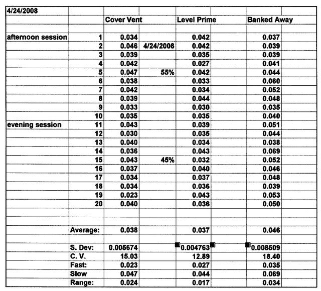
Most shooters with this vent location use care to avoid covering the vent. In the first set of trials I primed three different ways:
1. Prime banked to the outside
2. Prime level in the pan (I tapped the fixture to level the prime.)
3. Prime close to the vent and covering it completely.
The equipment used was the same: computer, physics interface, photo cells, and the fixture for holding the barrel and lock plate. The location for the photocells remained the same. Priming charges were kept covered until they were used.
The amount of the prime for this test remains .75 grain of Swiss Null B priming powder. (This amount has been shown to be the most consistent in previous tests.) The methods used are the same as in earlier tests. The video link below shows the process. (This is the same video as in Part 5.)
Because I was worried about fouling causing unreliable data, every effort was used to eliminate it as a variable. As in the earlier tests, the following steps were used to prevent fouling from affecting the data:
Wipe barrel between shots.
Second cleaning rod designed to wipe the vent liner.
Pan brushed.
Pipe cleaner used through the vent.
Compressed air through the vent.
While these steps may seem unnecessary for normal shooting, I felt justified when trying to obtain meaningful data.
Below is the data gathered for the low vent test:
It is worth noting that the trials covering the vent and the level prime were as close as they were. I suspect that there is no statistical difference between these two variations. Both, however were faster than banked away. They were 15-20% faster, in fact. I’ll draw no further conclusions until the high vent location is timed.
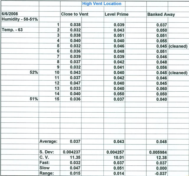
High Vent Test Phase
As I worked on the high vent phase, humidity became a concern. I was uncertain if I could maintain a comparable humidity when this phase was done. Earlier testing had been done with humidity in the 50-60% range. I waited for weather to help me, but found that by using an air conditioner in the garage I could keep the humidity within this range. Humidity at the beginning of the test was 58% dropping to 51% as the testing concluded. Temperature throughout testing was 63-64 degrees.
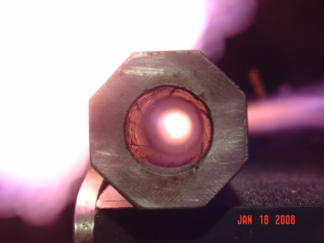
The only variable in this phase was the location of the vent. The lock plate and pan were rotated to place the vent as high as possible. The bottom edge of the exterior cone on the vent was well above the level of the pan. Please note the photo showing the vent hole.
The procedure was to time 15 tries with each of three powder locations in the pan – just as I did in the low vent tests. The tries were alternated as follows: powder banked away, level prime, and as close to the vent as possible. In this last location, I had intended to cover the vent, but .75 grain of powder was not enough with the vent located this high. I considered increasing the charge to 1.0 grains, but concluded that it would introduce another variable. I decided against that and used a pencil eraser to position the prime as close as possible.
After each location was timed 5 times, I removed the barrel and cleaned everything. Then I timed the next series. After 10 times I again cleaned, and then timed the last group.
The chart that follows shows the data gathered. As happened in the low vent trials, banking the powder away was slower and less consistent than level or close to the vent. Close positioning of the prime was decidedly faster and more consistent.
Conclusions:
These conclusions are those of the experimenter. You may have different opinions.
I wish to point out that every trial produced a report that sounded as one sound. The fastest (.032) and the slowest (.060) sounded the same. Even though one was almost twice as fast as the other, the sounds were indistinguishable. So my first conclusion is that the human eye and ear are terrible tools to use to evaluate flintlock performance. If differences can be determined by human senses, then the trial was indeed very slow.
The idea to bank powder away from the vent to improve flint performance is flawed thinking. In every test I conducted, the banked away trials came in last. Percentages varied, but banking the powder away was always slower. I found no evidence to support the old “bank the prime away from the vent.” (In the low vent test, banking powder away was 17% slower; in the high vent test, banking powder away was 23% slower.)
The idea that one should not cover the vent with priming powder because of having to burn through the vent instead of flashing through seems equally flawed. While I did not try to fill the vent, covering the vent did not cause slower times. The closer I could get priming to the vent, the faster and more consistent the results. In fact the consistency I found in positioning the priming powder close to the vent occured at all vent positions – low, level, and high.
The last conclusion involves the reason for this whole experiment – proper location for the vent in relationship to the pan. I found that the location of the vent in relation to the pan is far more forgiving that we have believed. Tests when the vent was extremely low or high both gave quick reliable ignition. A look at the chart below shows that all vent positions gave fast ignition when primed close to the vent (This is what we learned in the preliminary tests.) Also all vent positions gave uniformly poor performance when the priming powder was banked away from the vent.
————————–Banked way—————-Level Prime—————-Close prime
Low Vent—————–.046—————————.037—————————-.038
Level Vent —————.043—————————- * —————————–.036
High Vent—————–.048—————————.043—————————-.037
*I did not time level priming when testing the level vent/pan position.
I began this series of test thinking that the big variable would be the vent location. However, I am now concluding that it is of minor concern compared to the location of the priming powder in the pan. I still like a vent level with the plan flat won’t loose sleep over a pan a little high or low.
All of the work represented here was based on igniting the powder “artifically” using a red-hot copper wire. This was done intentionally to remove the variables in amount, quality, and location of the sparks. In reality the flint shooter must manage his lock to minimize these variables. Regardless of what the experiments show us, the shooter must place priming powder where his sparks will land. Time with his gun will determine this. However the shooter need not be afraid of priming powder too close to the vent – that is to be encouraged. It is far better to have the prime too close than too far away.