Our lock timing and photography project is finished. My son, Kevin, arrived from Denver on Thursday night. We began Friday morning working the bugs out of our equipment. Our goal was to time the shooters’ locks and take photos showing the spark production and where the sparks landed. Along with the photo, the owner got a paper copy of the lock times we recorded. The software allowed timing to the nearest 10 thousandths of a second.
Some unknown problems arose, but one at a time we seemed to solve them. Sometimes we could suggest cures for lock problems that we uncovered. An example was a lock with a badly worn frizzen and a strangely located retaining screw hole. Another lock was improved with a flint bevel change.
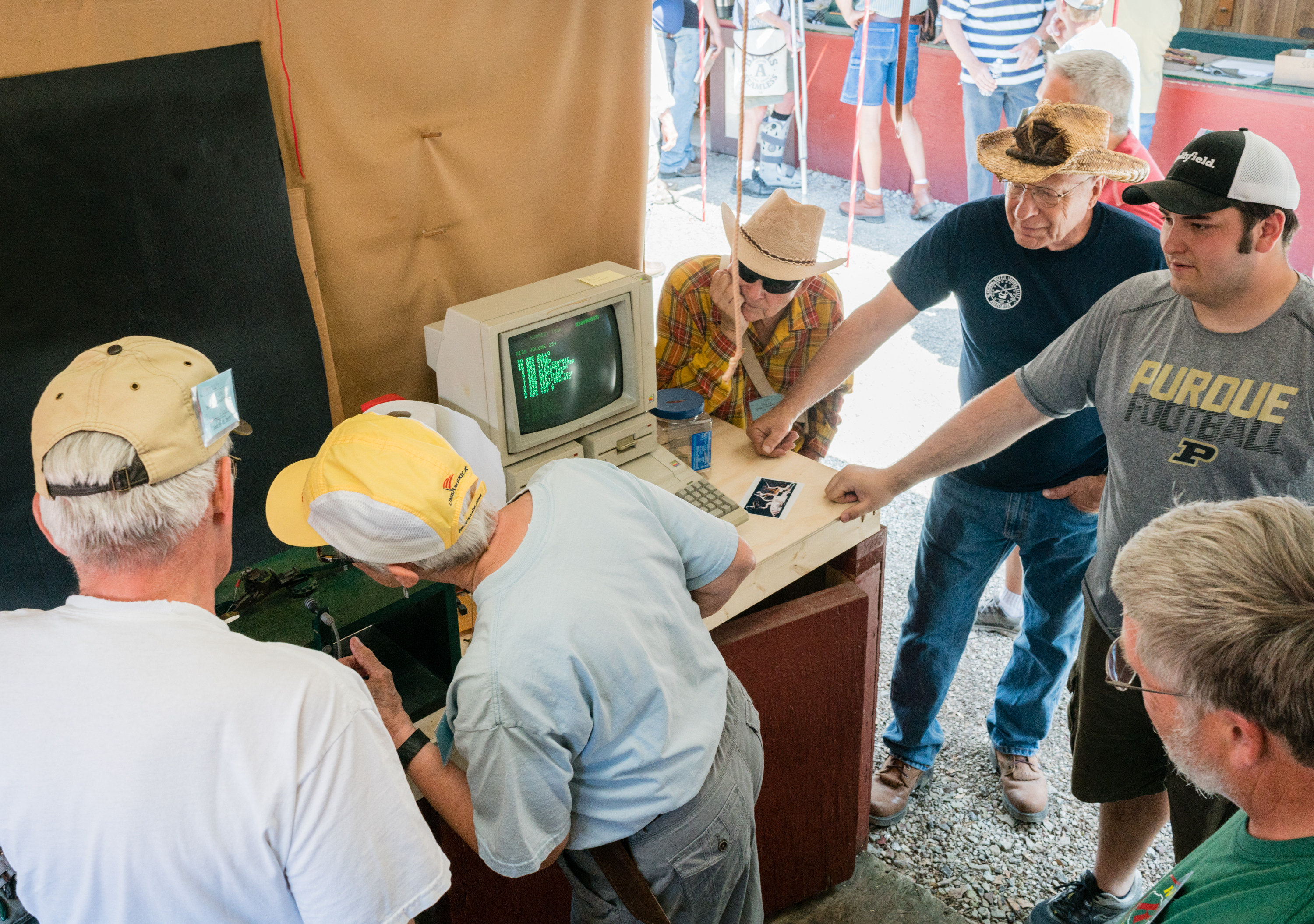
Susie Szynalski looking over the lock mount. Among those looking on are Dave Schnitker, Colton Fleetwood, Steve Chapman
Each different sized lock meant adjusting the plunger location. This meant time spent between locks. Because of this it was a pleasure to have a few identical locks in a row.
Our most difficult challenge was to alter the fixture to time a left-handed lock. The lock owner and I worked together. The advantage of the lock owner’s help was important. We could carefully eliminate any clearance issues caused by mounting the lock on the “wrong” side of the fixture.
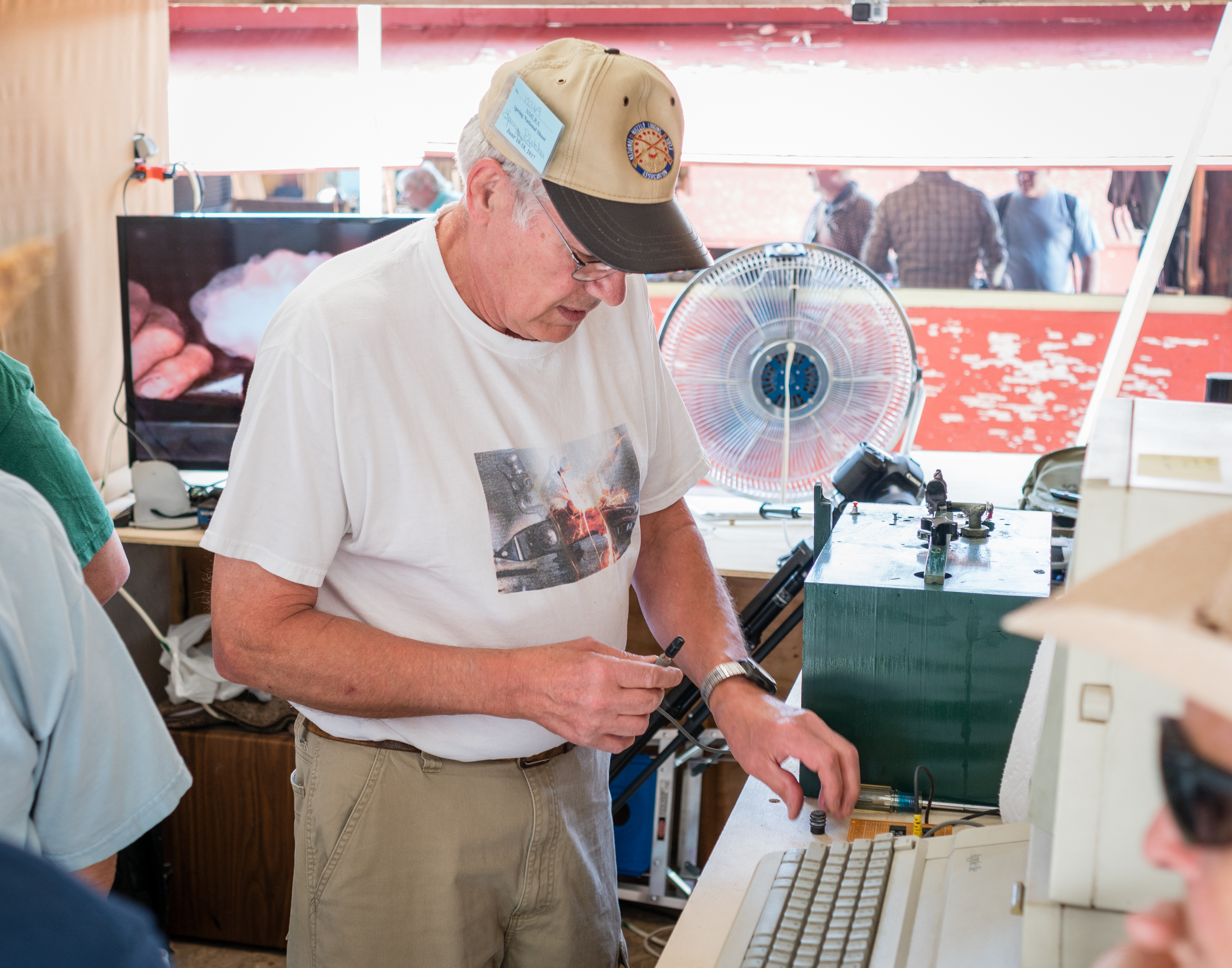
I’m replacing a photo cell. Behind me is the slow motion video we ran during the shoot.
One surprising addition was the chance to do a side-by-side test of Swiss Null B and a possible new Swiss product. I’ll be curious to hear what Swiss decides to do.
Kevin was a great help during this process. He managed the photography so I could concentrate on the lock stuff. He recorded stats on his computer until he had to catch his plane in Indy. Without him, the process changed to paper. At that point two other friends stepped up. Steve Chapman and Dave Kanger did the stat recording when I was by myself.
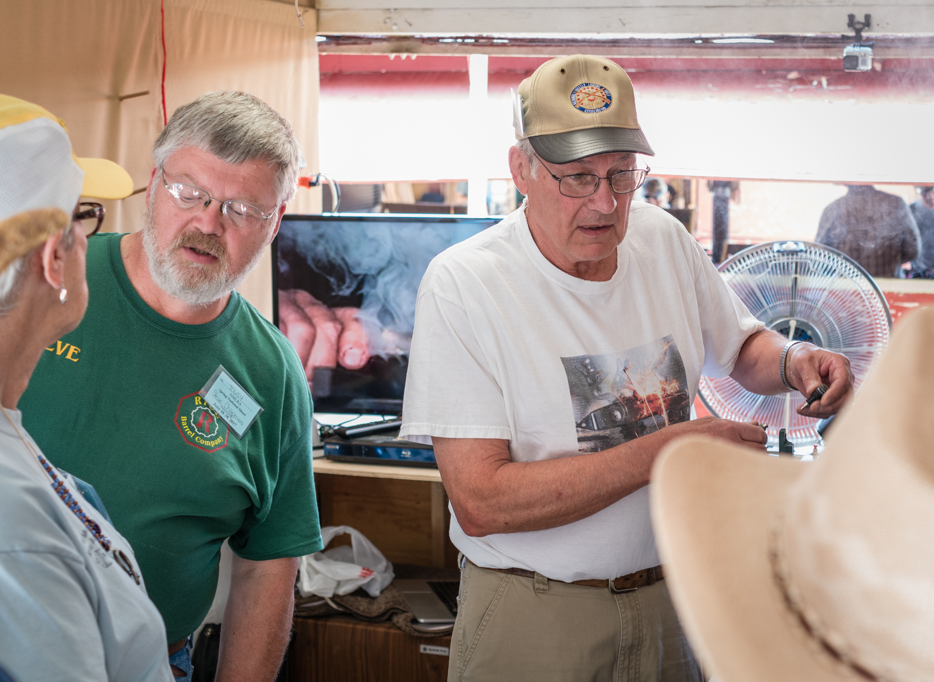
Steve Chapman helped to answer the many questions.
Kevin used Light Room to adjust the photos we handed out before he left. Those I took after he left I sent to Kevin this morning. When he works his magic on them I’ll email them to the owners.
This lock liked a bevel change.
All in all, I felt good about the project. We pretty much did what we hoped. I turned in the donations to Carrie in the office. I don’t know about the September Shoot. I need to get with the NMLRA folks and find if they want this repeated in the fall.
More than anyone else, I’d like to thank my son, Kevin, for his photographic help. You don’t see him in any pictures because he was busy doing his photo thing. His second set of eyes on the project helped with details, large and small. I also valued his advice in helping with explanations of the processes we used.
BlackPowderMag’s next project will be at the NMLRA Spring Shoot in June. I have received permission to time and photograph locks in Booth 112. Some of the details remain to be worked out, but I hope to be set up and working Saturday, Sunday, and Monday.
I plan to time a shooter’s lock for 10 trials and find the average. A photograph will be taken of the lock making sparks. We want to look and the quantity and quality of the sparks and see exactly where the sparks are landing.
I can handle most lock sizes from a Bess on down. Extreme sizes mean some fixture adjustments, but size is generally not a problem. The only requirement is that the lock be drilled and taped for a lock retaining screw. I will have 8-32 and 10-32 screws to hold the lock. If imported guns use metric threads, I may ask the shooter to bring his lock retaining screw with the lock.
I would like the owner to install a sharp flint, installed to best advantage. I will use Swiss Null B for the priming. (I have received special permission to have a small amount of priming powder in the booth. I will ask the head range office to watch the process to make sure he is satisfied.)
When we are finished, I hope to give the shooter a couple of things:
A copy of the lock times and average
A photo I’ll print in the booth
If you have an email address, I’ll email you a high density copy of the spark photo.
There is no fee, but we’ll set out a donation jar, whose contents will go to the NMLRA.
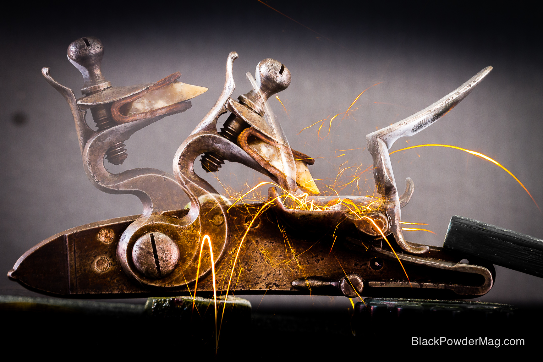
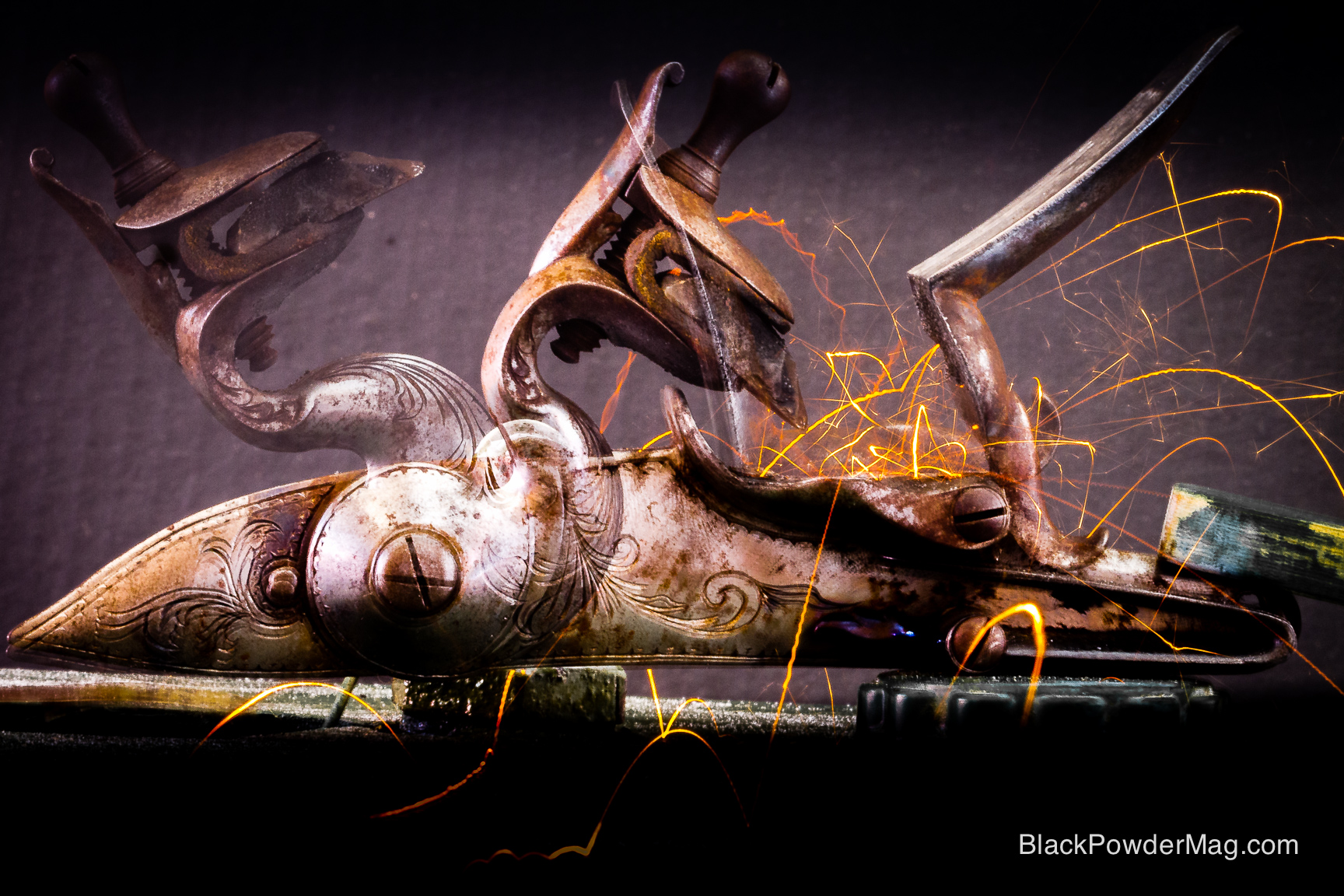
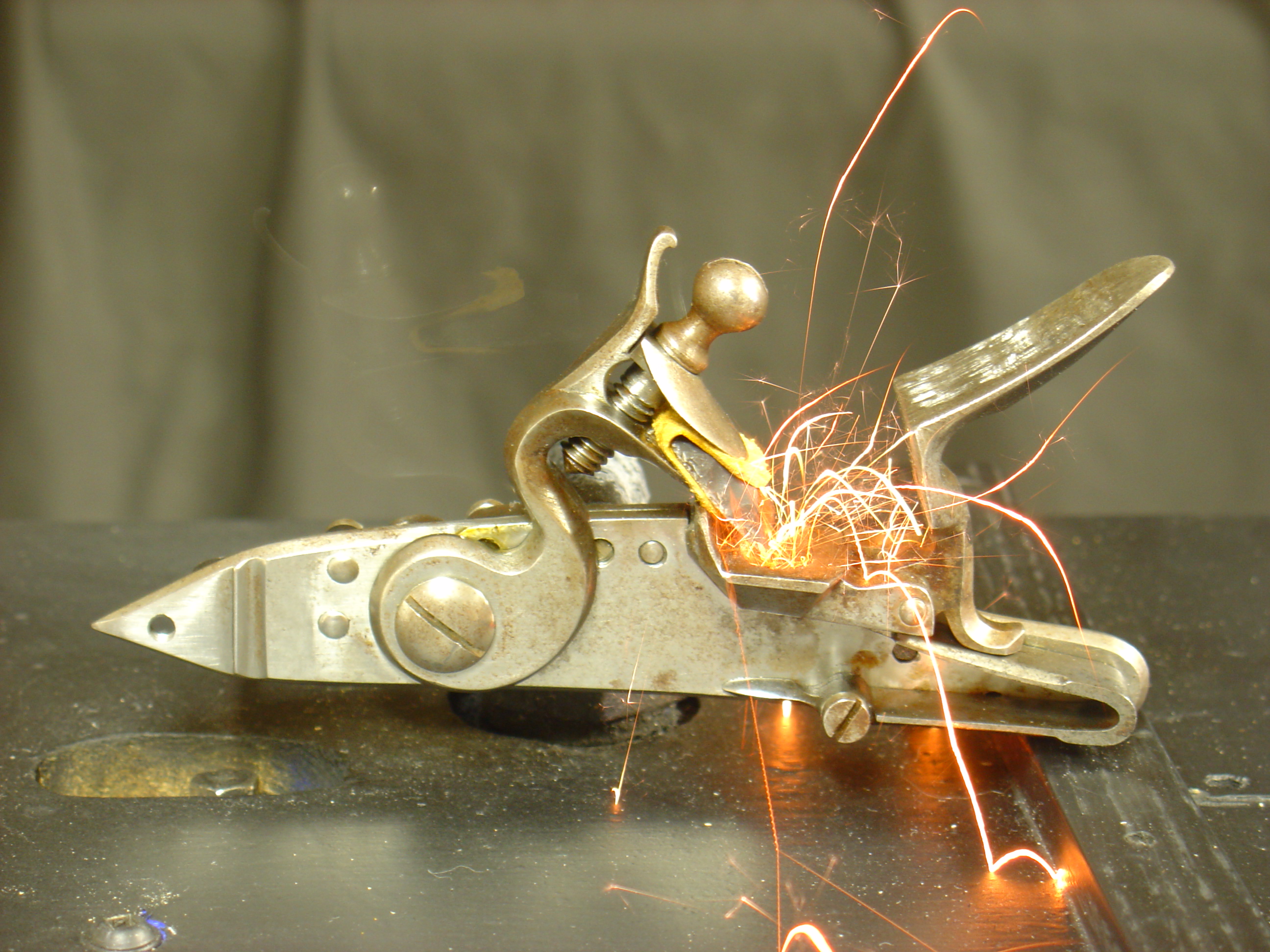
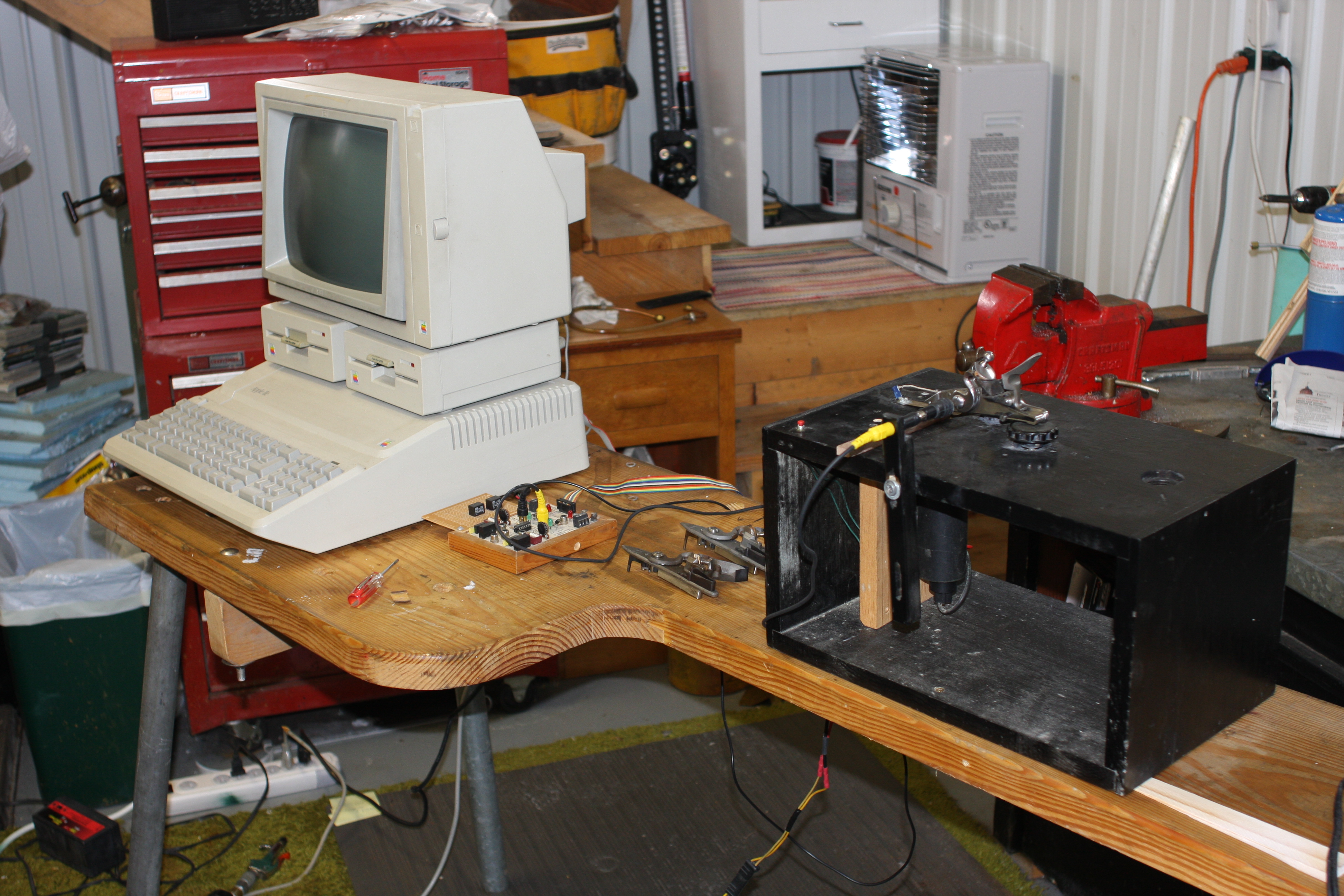
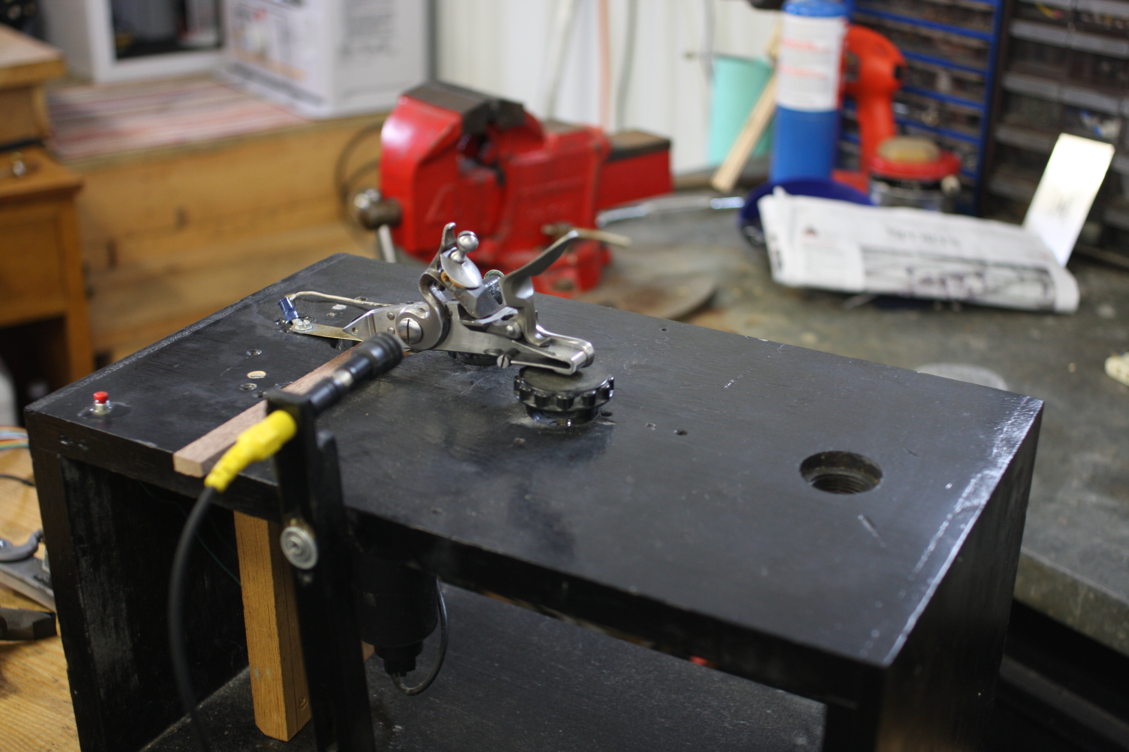
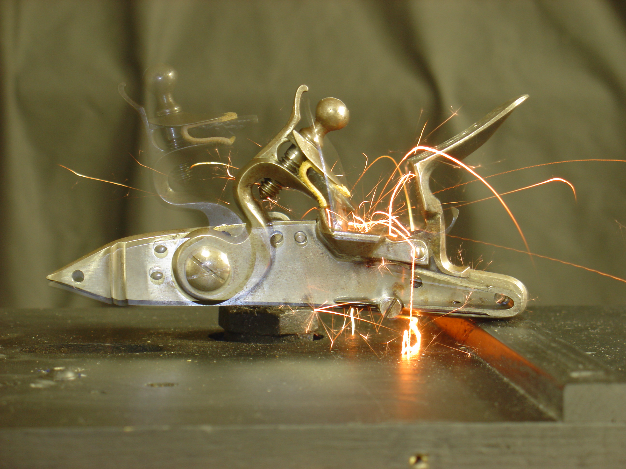
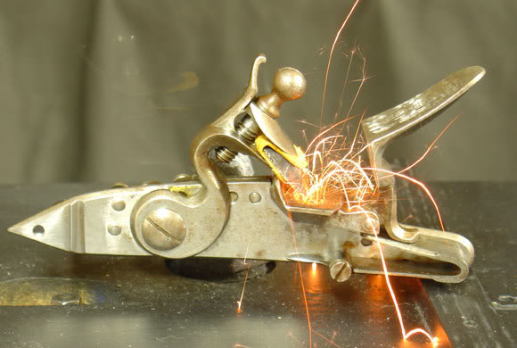
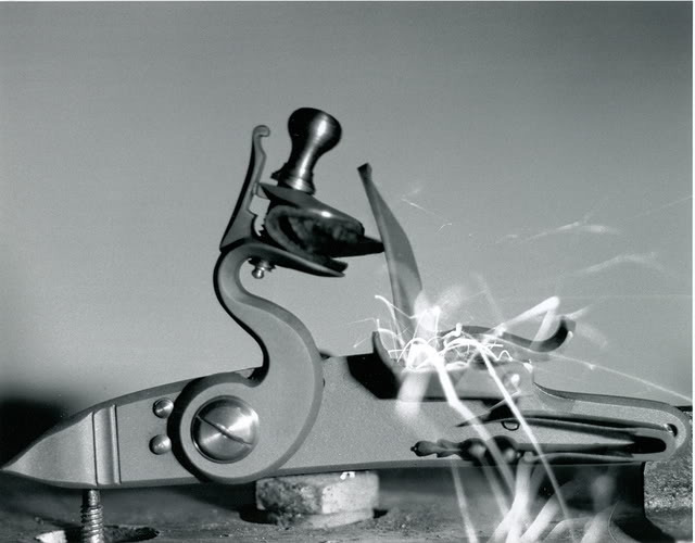
The photos included above show the equipment I use and a couple photos of one of my Silers’ sparks.
[box type=”note” align=”aligncenter” ]”A Study in Lock Timing” was originally a part of the Journal of Historical Armsmaking Technology, published by the NMLRA in 1991. It is reproduced here with permission from the NMLRA.,[/box]
I’d like to thank Gary Brumfield for his encouragement and advice during the data collecting and writing of this article.
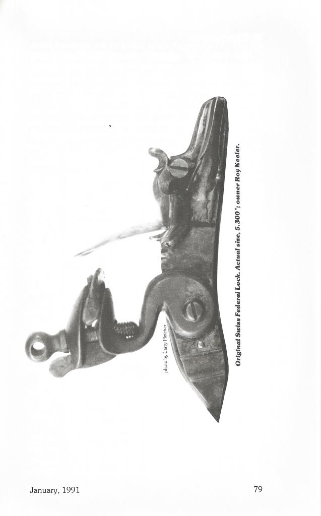
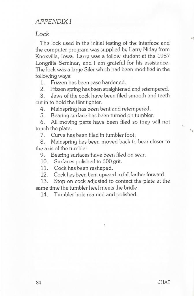
The Siler below is the lock used in the ’80s for the JHAT article. It has been fired probably thousands of times, but never was mounted on a gun. The article below listed all the modifications that were done when the lock was made. It has served as a test bed for many different experiments.
I still have that exact same lock. However only the plate and the cock are original. In 2010 Jim Chambers planned to change the cracked frizzen. By the time he was finished only the cock and plate were left. It continues to be my test bed lock.
[box type=”note” align=”aligncenter” ]Reprinted from MuzzleBlasts January 1990 by Larry Pletcher —- This article is the first in a series of three reprinted articles that measure a flintlock’s ability to ignite black powder. L&R’s Durs Egg and Manton locks are the subject of this article. Both performed well and provide a standard of comparison for flintlocks in future articles.[/box]
During the past two years I have had the opportunity to measure the ignition time on a number of different flintlocks. The locks varied from superb original locks to modern day reproduction locks. Some were in mint condition, while others were somewhat used.
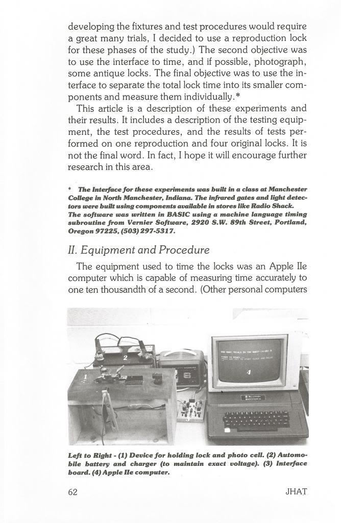
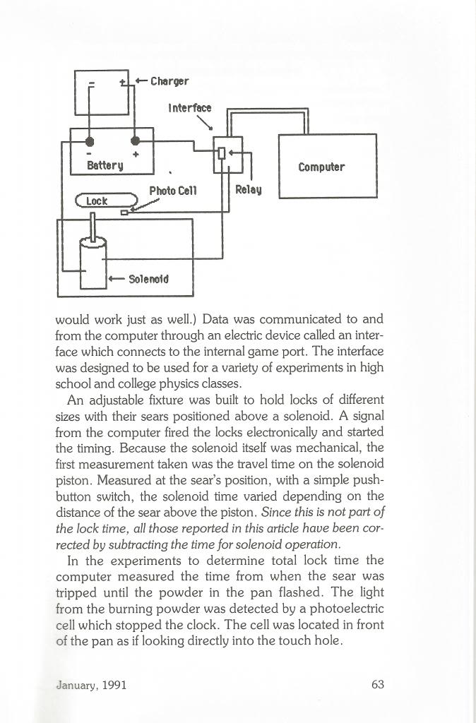
The equipment that I use to time locks consists of a computer and interface made to scientifically measure time in a high school or college physics lab. It has the ability to measure times to the nearest ten thousandths of a second. The lock is fired electrically, and time is measured until a flash in the pan triggers a photoelectric cell, stopping the clock.
The time taken by the computer interface is monitored and deducted from the lock time. The system seems to work well, and I have confidence in it.
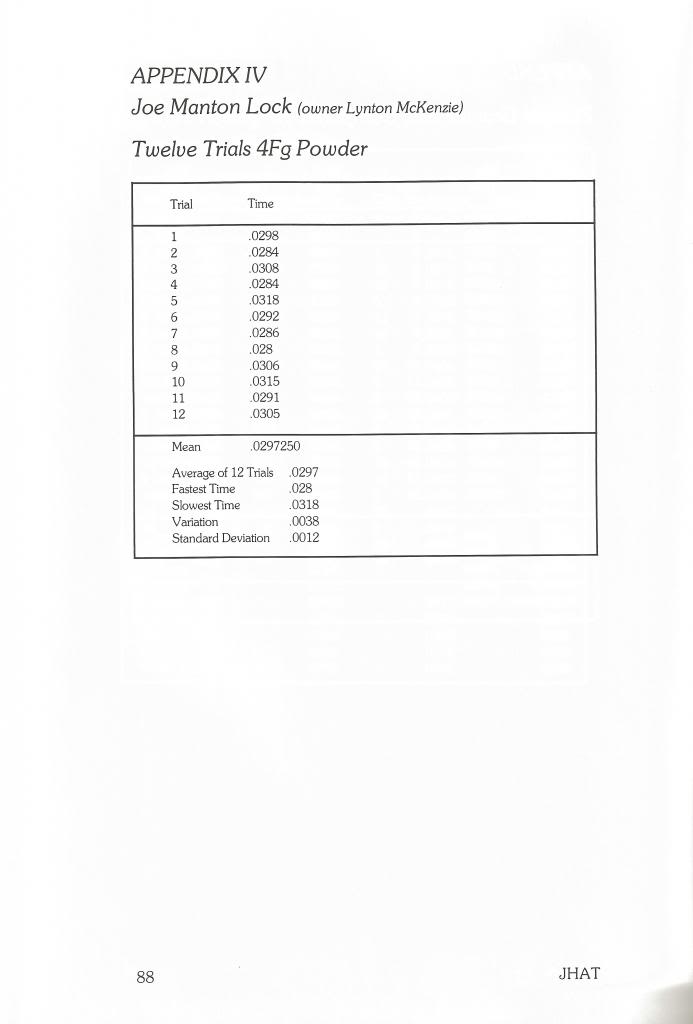
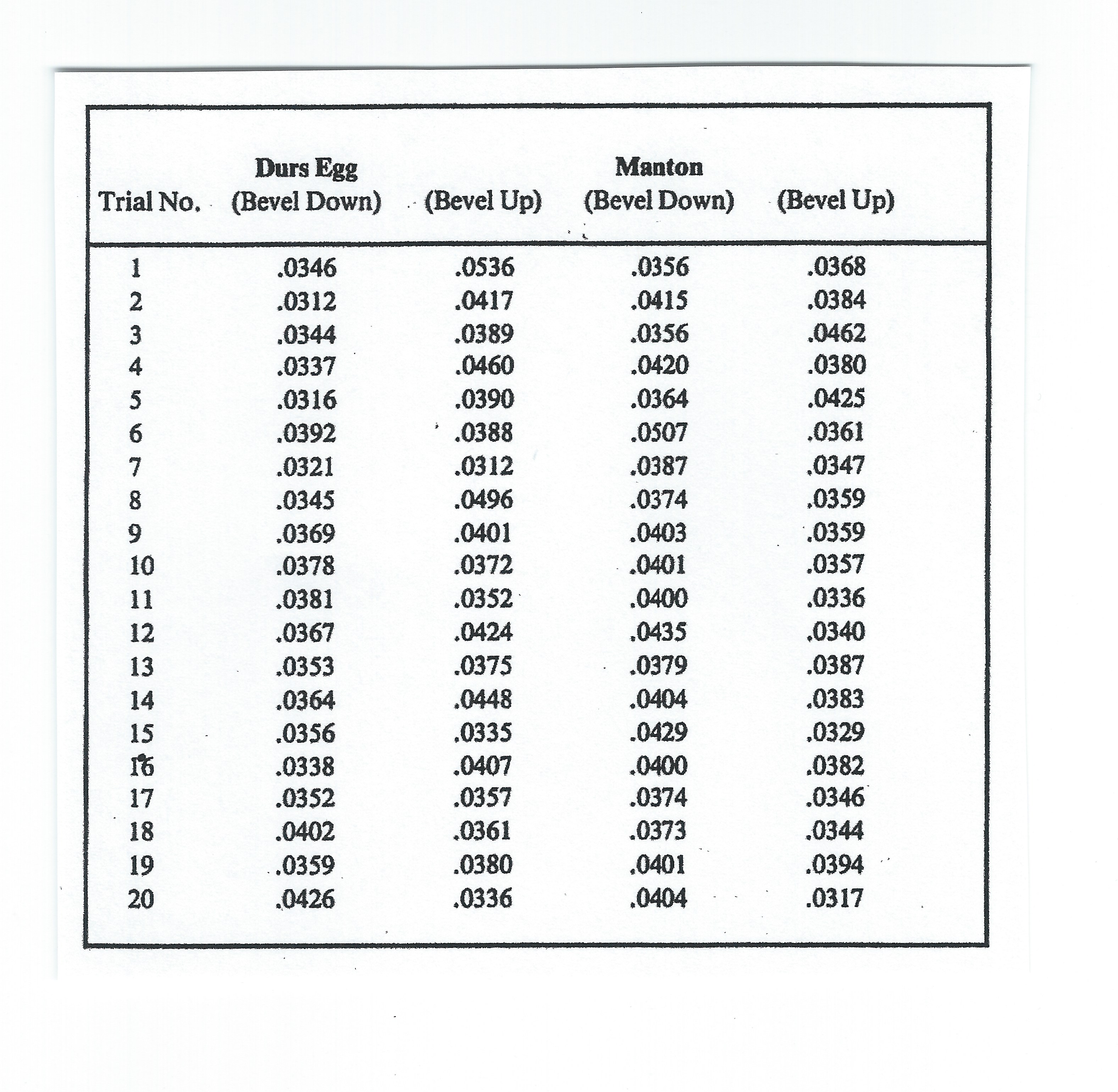
The Manton and Durs Egg flintlocks, made by L & R Lock Company, were used for this article, the first of a series of articles dealing with the timing of locks in current production. I received the Manton in the mail and the Durs Egg at Friendship. To my knowledge, neither lock received any special treatment beyond normal care during production.
The locks were primed with FFFFG powder, measured with a small dipper. The flint and frizzen were cleaned after each firing. Each series of 20 trials was begun with a new flint. Flints were knapped when they became dull during the test.
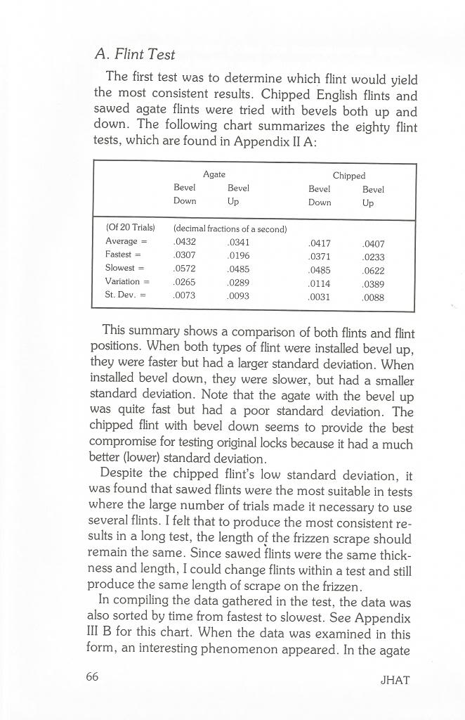
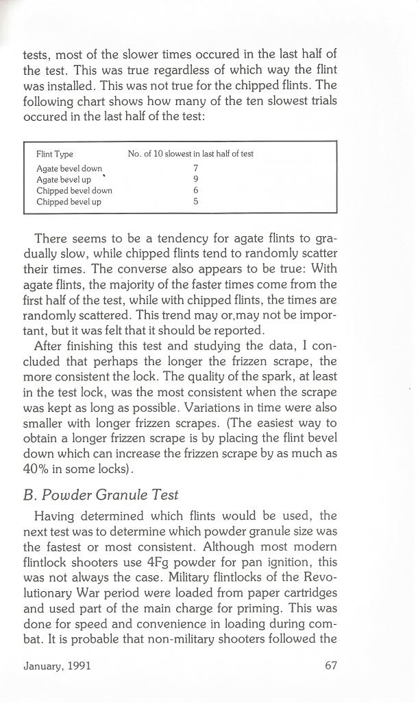
A series of 20 trials on both locks was done with the flint bevel up and again with the bevel down. I felt that most locks work better one way than the other, and I needed to report both ways. The following chart contains the results:
Chart of times recorded
I found myself liking both of these locks. With flints installed to their best advantage, they worked very well. Neither lock seemed to be hard on flints. Little knapping was required while running the tests.
The Durs Egg lock showed a preference for flints installed bevel down (up side down to most of us). Its best average was obtained in this way. Its variation was twice as small with the bevel down. Also, the standard deviation with the bevel down was half that when the bevel was up. If I were shooting a rifle with this lock, I would place the flint bevel down.
The Manton lock had a different preference in flint installation. It performed best with the flint bevel up (right side up). However it worked quite consistently with the bevel down too. Its variation shows that it was quite uniform in its operation. I would probably shoot the Manton bevel up, but would not be at a disadvantage if the bevel were down.
I think it’s interesting to note that the best average from each of the locks were only .0010 seconds apart. This is, of course, impossible to detect with human senses. In fact, after watching probably more than 800 trials with different locks, I cannot tell the difference between a normal time (.0390) and one twice as large (.0780). In order for me to visually detect a slow time, it has to be over .1000 seconds.
The point of all this is that if a shooter analyses a shot and thinks to himself, “That sure was slow”, it must have been VERY slow, probably three or four times as slow as usual. Anything less than this, the shooter would not have noticed. It is also possible that a slow shot was not caused by the lock at all. I am convinced that problems with touch holes cause more “slow” shots than poor lock ignition.
I believe that there is much to be learned about lock timing. This article just scratches the surface. In future articles I would like to study and time other locks currently available to shooters. I would be interested in ideas or study methods that others might have to extend what we know about lock ignition.
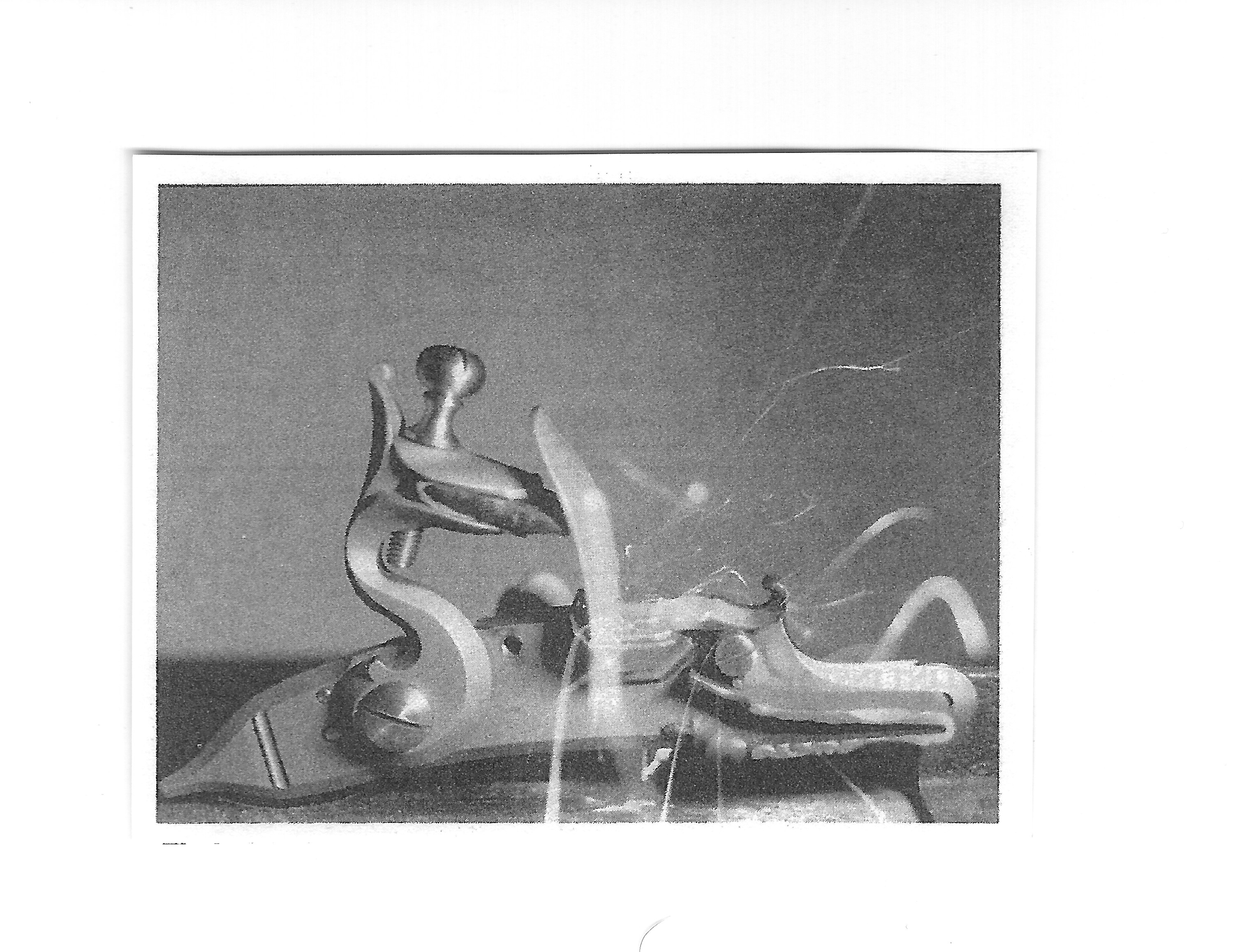
Photo #1
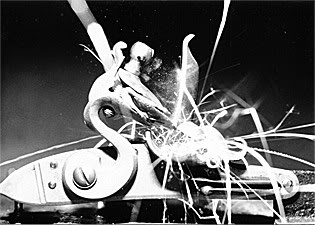
Shown .011 seconds after firing, the flint has just struck the frizzen. Notice the flint chips spraying off the contact area.
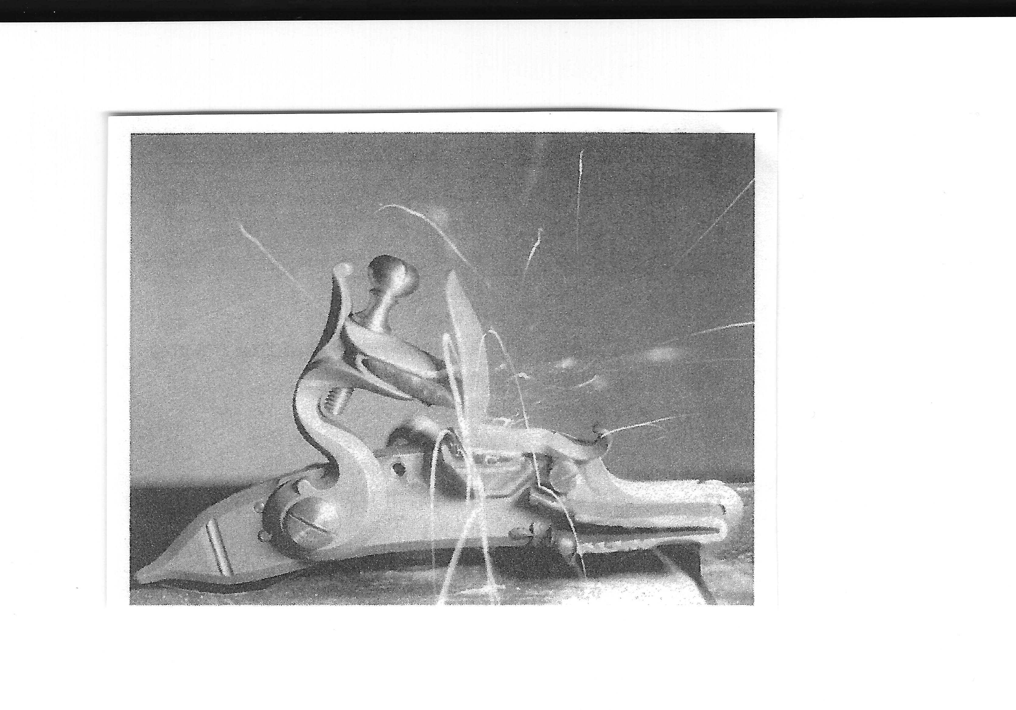
Photo #2
At .013 seconds the flint is nearing the bottom of the frizzen. Flint chips are still flying. Top jaw screw shadow shows where the parts will be when the lock is at rest.
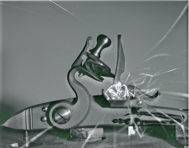
Photo #3
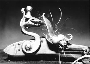
At .015 seconds, the flint movement is almost finished. However, the frizzen has considerable travel left.
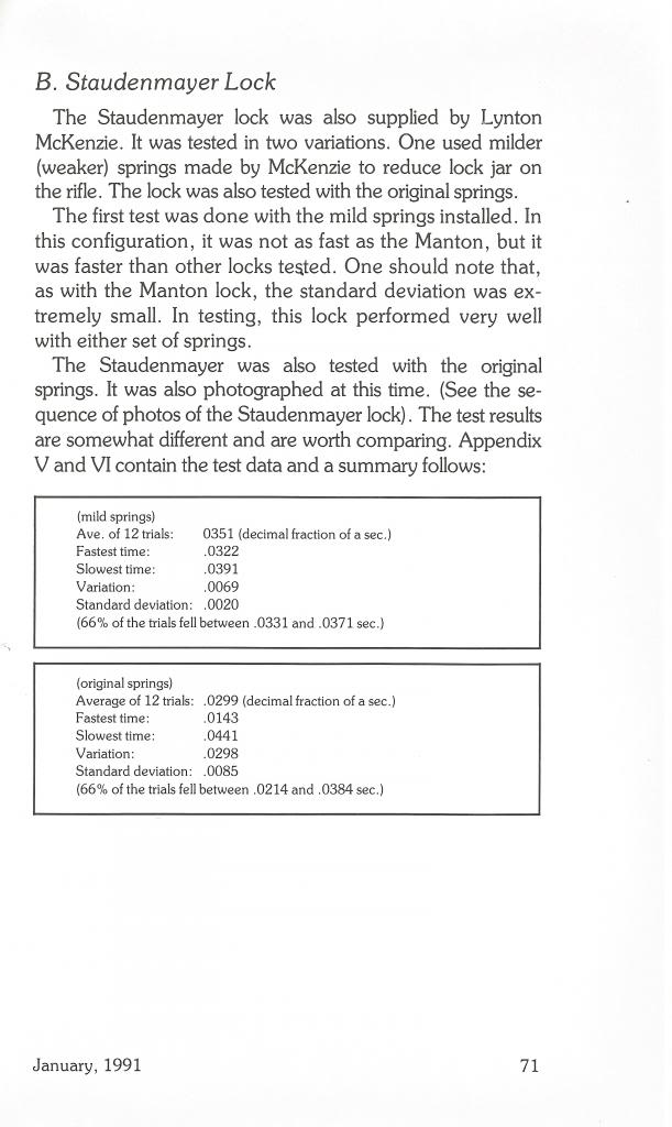
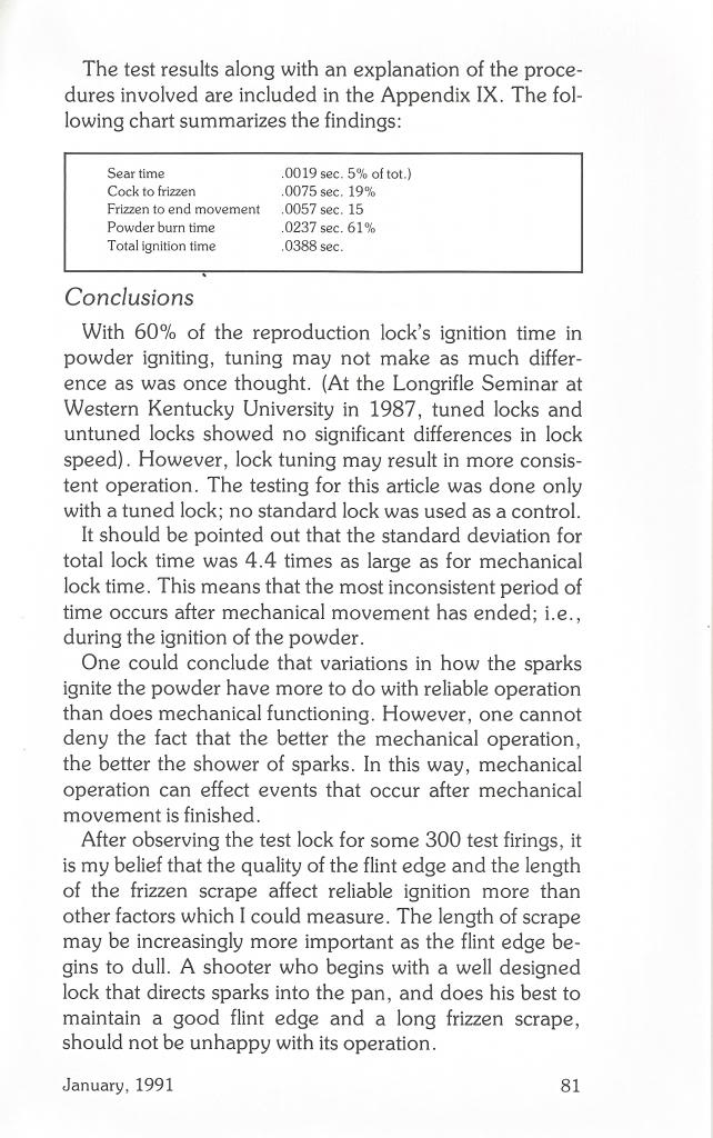
(Standard Deviation insert)
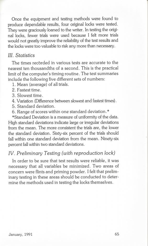
Standard deviation is a measure of consistency of the statistics. High standard deviations indicate large deviations from the average. The more uniform the trials are, the lower the standard deviation should be. Sixty-six percent of the times should fall within one standard deviation from the average.
(Photo explanation)
The photos were taken with the shutter open in a dark room. The computer fired the lock, caused a measured delay, and then fired the electronic flash. A faint shadow can be seen where the parts come to rest (top jaw screw and frizzen). The sparks are illuminated not by the flash but by their own light. They were not formed at the time the flash was fired. They show because the shutter remained open after the flash ended.
[box type=”note” align=”aligncenter” ]Reprinted from MuzzleBlasts September 1992 by Larry Pletcher —- This article is the second in a series of three reprinted articles that measure a flintlock’s ability to ignite black powder. R. E. Davis Company, black powder vendor in Pleasantville, Ohio provided the flintlocks used in this article.[/box]
Most of the testing and timing of flintlocks completed at this time has been done with modern reproduction locks. Because of their value, original locks should not be subjected to an extensive number of tests. Lock makers of today can’t help wondering how their work compares with the work done during the flint era. The Journal of Historic Armsmaking Technology Vol. IV has attempted to shed some light on this subject. The originals tested in Vol. IV can now be used as a benchmark by which reproduction locks may be compared.
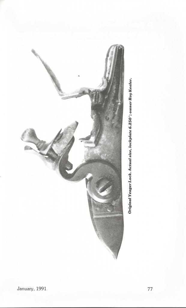
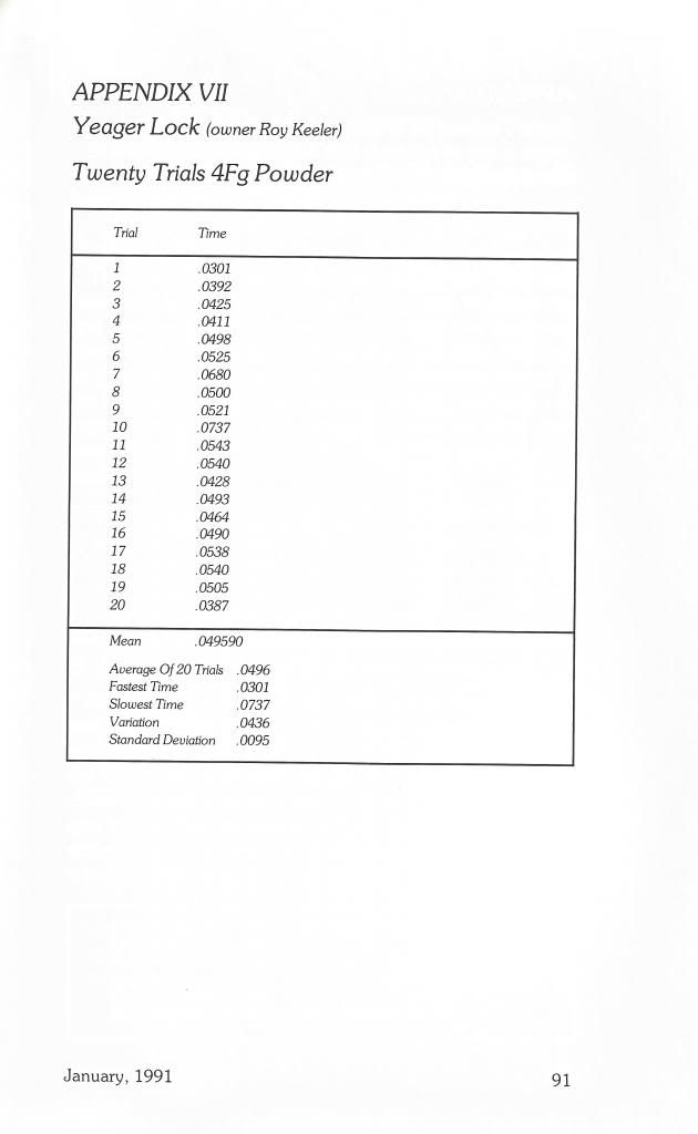
The three flintlocks tested in this article were made by R.E. Davis Company in Pleasantville, Ohio. The first, the Davis Yeager lock, which has an unbridled frizzen and a fly in the tumbler, can be found on many Yeager styled reproductions. The familiar banana shaped lockplate measures 6” by 1”. The lock would look at home on early German styled arms. Its Davis catalog number is #017.
The second lock is described by Davis as an Early Large Flintlock. It, too, is a large lock measuring 5 9/16” by 1 1/8”, and has an unbridled frizzen and a fly in the tumbler. The lock has Germanic styling and would by appropriate on transitional pieces. Its catalog number is #040.
The third lock tested in the Twigg lock (catalog #201). This English styled lock is 5 5/8 inches long with a bridled frizzen on which a roller has been installed. A stirrup is used on the tumbler. A pronounced camming effect can be felt as the cock is drawn back with little pressure required to move from half to full cock.
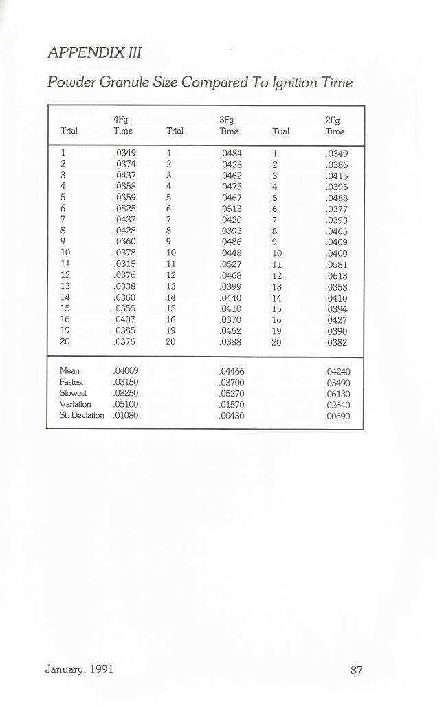
Testing was done with a measured amount of Goex 4Fg blackpowder. (The powder was stored at room temperature in a dry environment). Both flint and frizzen were cleaned between trials and flints were knapped when any noticeable change in their operation developed.
Photo 1
The Yeager illuminated by its own sparks. Notice the spark bursts at the left and upper parts of the photo. Also notice how well the sparks are directed into the pan.
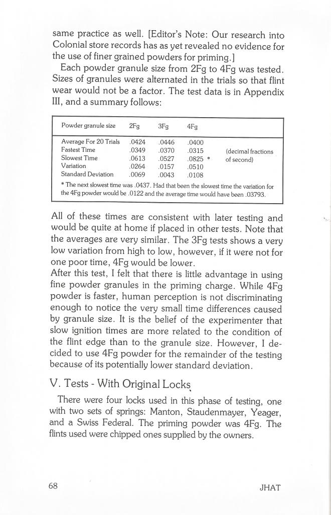
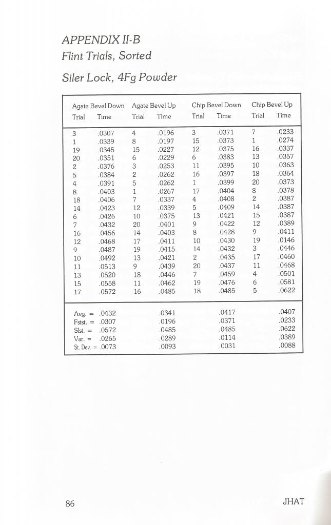
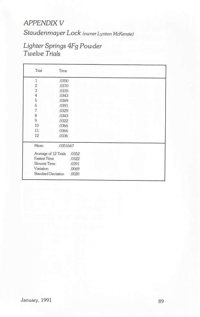
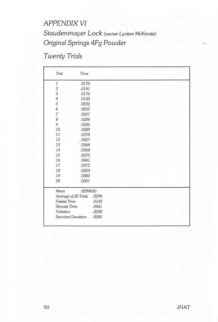
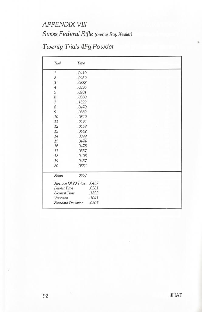
Since previous experience indicates that locks may show a preference for a particular way on installing flints, I again tested each lock with the flint bevels installed up and down. A series of 20 tests was conducted in each configuration. The complete test for each lock is in the appendix at the end of the article. The test results are summarized in the following chart:
Fig.1
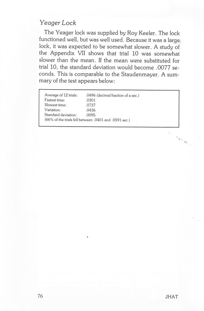
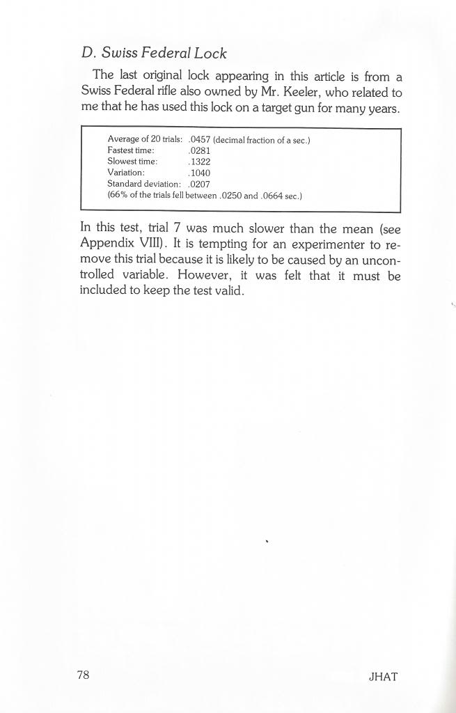
Summary of the tests conducted
The test summary showed that the first two locks had a preference for the flint to be installed with the bevel down. This was especially true for the Yeager. Its average, variation and standard deviation were all improved substantially with the bevel down.
Photo 2
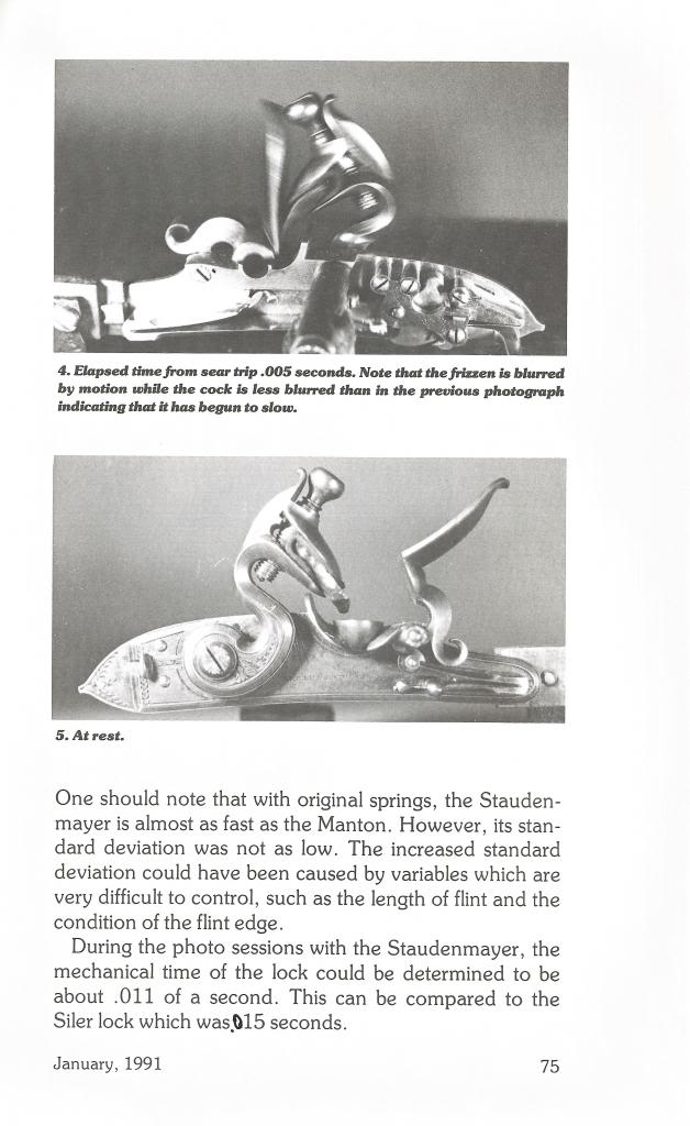
The lock is shown .010 seconds after the sear was tripped.
While the difference in performance was too small to be detected by human limitations, I would shoot this lock with the bevel down. My reason would be more for the improved variation than for the improvement in speed. I was very impressed with the Yeager’s variation and standard deviation.
Photo 3
The Yeager lock .002 seconds later.
The Early Large Flintlock was slower than the Yeager. Its average, variation and standard deviation were equal to the Yeager with the bevel up. This lock preferred the bevel down, but not to the same degree as the Yeager. I would probably shoot this lock bevel down, but I’m sure the difference would not be detected when firing. Its performance was quite satisfactory.
In analyzing the Twigg lock, one can see that the average times were almost identical. However, positioning the bevel up brought about the best standard deviation. The lock was almost twice as consistent this way. I would shoot this lock with the bevel up to take advantage of the improved standard deviation. Because the Twigg likes a long flint, I had to make sure the flint installation did not allow the top jaw screw to hit the frizzen. I liked this lock almost as much as the Yeager.
When shooters discuss the speeds of various locks on the market, one often hears the theory that large locks are slower than small locks because there is more mass to accelerate. While this theory may hold some truth, the Yeager looks like the exception. In spite of its size, the Yeager (with the bevel down) performed as well as a number of smaller locks I have tested. With the flint installed bevel up, its performance was slower and more nearly what I would have expected of a larger lock.
* * *
The accompanying photos allow another statistic to be measured. I attempted to calculate the speed of the flint as it travels down the frizzen by measuring the distance the flint traveled in photos. A proportion was set up using the following format:
Fig .2 – Proportion used to calculate flint speeds
Photo Frizzen Length Photo Flint Travel
————————- as ———————–
Actual Frizzen Length Actual Flint Travel
Fig.3 – Speeds of flint desending the frizzens of the Yeager and Twigg
Lock: Upper Flint: Lower Flint:
Yeager 15.6 ft/sec 12.1 ft/sec
Twigg 13.2 ft/sec 20.7ft/sec
The Yeager flint is apparently slowing down as it travels down the frizzen, while the Twigg’s camming effect allows it to overcome friction and actually accelerate. This did not prevent the Yeager from out-performing the Twigg both in speed and consistency, however. Apparently, raw flint speed is not the answer to lock performance. So far, I have tried to measure flint speeds on only three locks. I hope tests such as these can be substantiated by additional testing.
I hope these lock-timing experiments will cause us to think about the factors that cause locks to perform well. Obviously, there are considerations which we have not measured and perhaps can never isolate. Maybe by experimenting with different modifications, we can identify some characteristics of successful locks. In a future article I will report on modifications done to one of the popular locks on the market.
[box type=”note” align=”aligncenter” ]Reprinted from MuzzleBlasts December 1992 by Larry Pletcher —- This article is the third in a series of three reprinted articles that measure a flintlock’s ability to ignite black powder. This article deals experimental Siler flintlock components from Jim Chambers, riflemaker and vendor of black powder parts.[/box]
Most of us, at one time or another, have wondered what factors cause locks to produce good results. Obviously, there are considerations which we have not been able to measure and maybe can never isolate. In this article, I would like to look at some factors
Photo 1: The flint is just about to begin contact with the frizzen. Two thirds of the mechanical time is complete.
which have not yet been measured. By experimenting with different modifications, perhaps we can identify some characteristics of successful locks.
This month’s experiment was done with the help of Jim Chambers. He supplied me with a large Siler lock with replaceable tumblers and cocks. This gave me a chance to alter one variable at a time to see what change it would make. I was provided with the following:
		a Siler lock assembled by Mr. Chambers
		a stock Siler tumbler
		a modified Siler tumbler
		a Chambers tumbler
		a stock Siler cock
		a Chambers cock
(The mainspring needed to be repositioned depending on which tumbler was installed. Mr. Chambers modified the lockplate allowing this change to be made easily).
With these parts to use, six possible combinations could be tested. I began by testing to see which way the flint bevel should be placed to work the best. The flint installed with the bevel up provided the best performance. Each test thereafter was done this way.
Photo 2: This photo was taken .002 seconds later than Photo 1.
Photo 3: This photo was taken .002 seconds after the previous one. The flint fragment located just below the flint in the photo demonstrates a variable always present – a constantly changing flint edge.
As in earlier articles, testing was done with a measured amount of Goex 4Fg powder. (The powder had been stored at room temperature in a dry environment). The flint and frizzen were cleaned between trials. Flints were knapped when any noticeable change in operation developed.
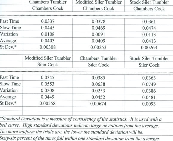
A series of 20 trials were conducted with each possible combination. The following chart provide a summary of trials:
An examination of the charts leads to a number of conclusions. First of all, the modified Siler tumber (test 2,4) had a pronounced camming effect as the lock was brought to full cock. In fact, one had to practice finding the half cock notch. The Chambers tumbler had a camming effect to a lesser degree; the stock Siler tumbler had none. Since the difference in results 1,2,3 were so small, the camming effect may not add a great deal to the functioning of the lock.
The Chambers cock seems to make a difference in the speed and standard deviation in these tests. Wile the tumbler does make a small difference, the first three combinations (in both speed and standard deviation) used the Chamber cock. This
cock had a lightly longer throw than the Siler cock. The extra length seems to be achieved by lengthening the neck; the angle of the jaws of the cock does not appear to have been changed. Whatever the difference, the Chambers cock appears to be an improvement. If I were buying a lock from Jim Chambers, I would specify the modified tumbler and Chambers cock.
The standard deviation in each combination seems to increase as the time increases. (Tests 1 and 2 were the only ones which did not follow that pattern). The standard deviation on tests 2 and 3 were very good. They would compare favorably with most locks today.
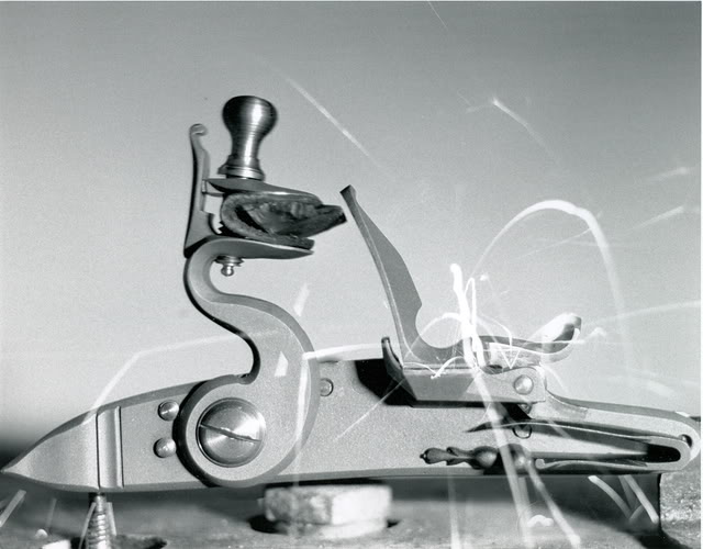
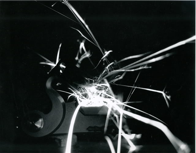
In June of 1990, I attended the NMLRA’s Gunsmithing Workshop & Seminar held at Northern Kentucky University. One topic discussed dealt with position of sparks when a flintlock is fired. One instructor proved to us, using ultra high speed video, that sparks from a well-made lock literally coat the pan! Photo Number 4 demonstrates this phenomenon quite well. This photo is illuminated only by sparks produced by the lock. Note that the pan is white with sparks.
Photo 4: Taken without any flash, this photo is lit only by sparks. It is safe to say that this lock puts the sparks in the right place.
Another spark phenomenon discussed was a secondary burst. The spark appears to fly away only to burst into three or four new sparks. This can be seen in two of the photos.
Measurements from the photos can be used to determine the speed of the flint as it travels down the frizzen. Using photos 2 and 3, I measured the distance traveled during the .002 seconds that elapsed. I set up a proportion to convert distance to the scale of the lock. This gave a flint speed of 24.2 feet per second. By measuring other locks in the same way, perhaps we can determine how much effect flint speed has on spark production.
As I have stated before in other articles, I think we are just scratching the surface in learning what makes locks work well. There is much to learn. As before, suggestions are welcome and may be sent to 4595 E. Woodland Acres, Syracuse, IN 46567.