Category: Experiments & Tests

Experiments and tests from Larry’s Lab.
Myth busting for the Black Powder community.

  • Flint Elk Rifle — Part 2

    Flint Elk Rifle — Part 2

    Rifle has a .58″ Sharon barrel, L&R flintlock, custom stock built by Steve Chapman

    When I wrote “Flint Elk Rifle” in 2016, I explained the water test that Rick had done in Colorado. Back in Indiana Steve Chapman and I thought through a number of things we wanted to learn in our water test. Our main goal was to compare penetration and expansion of the ball. Our thinking was that with a ball as large as .58” more expansion wasn’t necessary and might limit the ability to penetrate far enough for large game.

    We decided to compare a pure lead ball with an alloy ball in our test. The alloy ball was cast from melting down “hard cast (alloy 2)” pistol bullets from earlier reloading days. The result was a ball that weighed 273.5 to 274 gains. They weigh about 7 grains less than the pure lead ball, but we felt it was not enough different to worry about. I cast enough pure and alloy balls for our test.

    We set up in Steve’s back yard with a shooting bench for the shooter, a bench that held 10 one gallon milk jugs full of water, and three cameras. A GoPro camera would do a video, a Canon would take stills at about five per second, and another Canon would do an HD video.

    We planned to fire the pure lead ball first and recover the ball. Then we would replace the jugs and fire the alloy ball and recover it. With all cameras ready and Eric helping run the cameras, Steve fired the pure lead ball. There were no surprises here. The ball was found in the fifth jug, having destroyed the first four. We replaced the jugs and got ready to shoot the alloy ball. Our initial thoughts were that the alloy ball would penetrate more jugs than the pure lead ball and expand less. In fact we thought that the ball might deform so little that it might be reused.

    The alloy ball shot surprised us. Not only did it penetrate farther than the pure lead ball, it went through all ten jugs and ended up in the woods well beyond Steve’s yard. So, we could not recover the ball to compare expansion. We did notice that the ball destroyed the first 4 jugs and then simply holed the remaining 6 jugs. We have no idea how many jugs would be necessary to stop and recover the ball.

    Below are the series of stills of the alloy shot. The action occurs in the .2 second between the first two frames. Fragments of jugs and caps are in the air, and water can be seen coming out of the tenth jug. However the water eruption increases through the next stills.

    Last still before firing.
    #1 First still after the shot.
    #2 Second shot
    #3 Third shot
    #4
    #5
    #6 All later shots are covered by water and by smoke from the gun.

    Conclusions: It’s safe to say that the alloy ball (#2 alloy) penetrated far better than the pure lead ball.  The load of 90 gr. Swiss fffg was chronographed earlier at nearly 1700 fps. The alloy ball penetrated 5 more jugs than the pure lead ball, but we have no idea how many more jugs we would have needed to capture the alloy ball in a jug.  Steve reported that the ball loaded as easily as the lead ball.

    Neither Steve, Eric, or I have hunted elk, but we feel that this gun and the alloy ball load would be an ideal setup for elk.  Note that we used primitive sights and think the sights should determine the effective range of the gun.

    The following video is the #2 alloy ball fired at the 10 jugs. It destroyed the first 4 jugs and holed the next 10. We obviously could not recover this ball.

    Larry Pletcher, editor

  • Flint Elk Rifle

    Flint Elk Rifle

    The history of this rifle began years ago when my friend Rick Shellenberger in Colorado cleaned out an old muzzleloading shop. Among other items, he brought home 2 Sharon .58 caliber rifle barrels. Both were rifled at 1 turn in 72 inches. These barrels have eight lands and grooves. Rick kept one barrel and gave the other one to me.

    Back in Indiana, years passed until I began collecting parts to complete the rifle. My friend Steve Chapman gave me hard maple rifle stock. It was a half stock with a 1 inch barrel channel and a mortice cut for an L&R lock. Steve suggested we look for an L&R lock that matched the mortice, and both of us like Davis triggers. I bought parts at the Friendship spring shoot, and Steve took them back to his shop.

    Steve knew that time wasn’t a factor, and had a number of other gun-making projects to finish ahead of mine. When he began to work on the gun, a couple decisions were made.  One decision was to use Tom Snyder’s vent coning tool to make the vent.  This process consists of drilling a 1/16″ hole, inserting Tom’s threaded pin, and installing the cutter through the open breech.  We used a cordless drill to cut the internal cavity.  The cavity is very similar to Jim Chamber’s vent liners.

    The barrel was shortened to 32 inches as stock proportions were considered. Considerable wood was removed to give the rifle much better lines.   Steve poured a very nice pewter nose cap. A removable aperture rear sight was used to help a pair of 70 year old eyes.

    Here you can see the .58 caliber hole and the crown Steve cut.
    Here you can see the .58 caliber hole and the crown Steve cut.
    Final shaping of cheek piece
    Final shaping of cheek piece  (Photo S Chapman)
    Lock installed, wrist shaped
    Lock installed, wrist shaped  (Photo S Chapman)
    Barrel Lugs
    Barrel Lugs  (Photo S Chapman)

    The finish used on the stock was a mixture of stains that Steve likes, and I like the way the stock turned out. I didn’t quiz Steve on the exact mixture, but I know that it was a mixture of Homer Dangler’s stains.

    Cheek piece
    Cheek piece  (Photo S Chapman)
    Pewter nose cap
    Pewter nose cap  (Photo S Chapman)
    Forearm and nose cap
    Forearm and nose cap  (Photo L Pletcher)
    Lock area
    Lock area  (Photo L Pletcher)

    When the rifle was finished, we went to the Stones Trace range to sight it in. With the rifle shooting to point of aim, we played with powder charges. A Swiss load of 90 grains of fffg gave us almost 1700 feet/second. I expect that a load of ffg may be found that will give similar velocities with less pressure. At this writing, I expect to experiment with different powder brands and grain sizes. Right now it is a potent rifle at both ends.

    20160921_103154

    Rifle by the hearth (Stones Trace Historical Society
    Rifle by the hearth Stones Trace Historical Society  (Photo L Pletcher)

    As we finished up our chronograph session, Steve said, “ Since this gun puts the ball at the top of the front blade, you could head shoot squirrels with it, or bark them.”

    I said, “Well maybe not with 90 gr. of Swiss fffg.”

    “Yah,” Steve said. “Wonder what it would do with a squib load, like maybe 30 gr.”

    So, we chronographed a 30 gr. Swiss load of fffg. This load drove the 280 grain ball an average of 870 fps. Maybe we need to think lower for a squib. On a whim, we also clocked a load of 30 gr of Goex. It averaged less than 500 fps. This does seem more squib-like.

    As a side bar, my friend Rick in Colorado stocked a rifle with the other .58 barrel that I mentioned at the beginning of this post. Rick wanted to recover a ball to see how much it expanded. During my time visiting him, we filled a garbage can with water and fired a 90 gr ffg load down into the can. The garbage can split down the side, but we did recover the ball. We taped the can together as best we could and fired a .58 cal. mini ball.  Below is a pic of the expanded ball with the mini ball before and after.  These rifles will make a big hole in about anything in North America. If my health and physical condition permitted, this would be the gun I’d use for elk.

    Left is the .570 ball before and after recovery. On right is a mini ball for comparison
    Left is the .570 ball before and after recovery. On right is a mini ball for comparison
    Rifle by the hearth
    Rifle by the hearth  (photo L Pletcher)

    Back here in Indiana, Steve and I will need to do some form of Rick’s water experiment. We haven’t decided what we want to destroy, but it will be something filled with water.

    Steve Chapman is a close friend with rifle-making and machinist skills.  We have worked on many projects and experiments together.  Whenever a project needs more hands, Steve is the person who helps.  He usually pulls the trigger in any test that measures accuracy.  While we both fired this gun for accuracy, Steve’s shooting skills have been necessary in many of our experiments.  Steve’s many skills have been a benefit in many of these experimental articles.


    Future tests, thoughts,etc

    Thought: We might learn more from a different water test. We’re thinking of a row of milk jugs filled with water. A .308 is caught in the fifth jug. We think the .58 will do better.

    Also: Build a water box to hold 1 gallon plastic bags. With this setup we could repeat tests and compare different calibers and loads. Compare the 90gr ffg Goex load and the 90 gr fffg Swiss load.


  • Two Hole Vent Test

    Two Hole Vent Test

    This test is a long time coming.  A couple years ago at CLA, Steve Chapman and I were looking over a flint gun made by Allan Sandy. The vent Allan used had two smaller holes located horizontally.  Allan said the vent was internally coned but used two .052″ holes.  Allan said he didn’t know whether it was faster or slower than a normal vent. My reply was that I could time it.  Allan offered to provide me a vent, and on the way home, Steve and I planned how the vent would be tested.

    Time passed with many interruptions in the way.  In the meantime Fred Stutzenberger entered the picture.  I believe Fred saw the “double-hole vent” on Sandy’s table at the same show that we did. Fred however, was more prompt than we were and published an article on the vent in the August 2014 issue of MuzzleBlasts.

    Without great detail, Fred’s article compared Allan’s double-hole vent with a single-hole vent that had the same area as the sum of the two smaller vents.  His findings showed that shots fired with the double-hole vent had slightly higher velocities than the single-hole vent even, though the vent area was the same.  The “choked-flow principle” (comparing circumference to area) is the likely cause.  Fred explains this better than I do; please read the article.

    Our testing focused only on ignition speeds.  We compared ignition time of the double-hole vent (two .052″ holes) and the single-hole vent (.073″) Both vents have the same area, but vary in their circumferences.

    2015-11-05-18-58-52

    The main question I have is, “If the choked flow principle tends to restrict flow leaving the vent, might it also restrict flow entering the vent, causing slower ignition?”

    We used a 10″ barrel stub with a small Siler flint.  The test used a double-hole vent with .052 holes and a single-hole vent with a .073 hole.  We did 10 trials each and lit the pan with a red hot copper wire.  Our reason for this was to prevent a changing flint edge from entering into the test.  The single .073 vent was better both in speed and consistency.

    Before finishing, we ran 5 trials each in which the pan was ignited by the small Siler.  In those trials the single-hole vent was better, but by a smaller margin.  None of the trials sounded abnormal to the ear.  No matter the range from high to low, human senses could not tell the difference.  In fact, Steve tried to guess and was invariably wrong.

    Here you see the shield that prevented both photocells from triggering when the pan flashed
    Here you see the shield that prevented both photocells from triggering when the pan flashed

    Interpreting the results can sometimes be misleading.  In this case, I like the single-hole vent.  However, I do have two doubts. (1) I have questions about the reliability of a vent as small as .052”.  A double-hole vent with larger holes might alter the result.  (2) I wonder if the shape of vent’s exterior would change the result.

    The included photos show the fixture and the position of the photo cells used in the timing.  The photo cell at the pan trigger the start, while the photo cell and the muzzle triggers the stop.

    2015-11-05-18-57-14

    The last pic is a close up of the vent.  These holes are .052″.  BTW, the stock is a heavily mutilated factory second supplied by Jim Chambers. It was important because it allowed the sear to be struck from below by the plunger. It also allowed us to use a small Siler lock for an earlier test.  At that time it allowed three different locks to be tested using the same lock mortice.

    To conclude, I’d like to thank Allan Sandy for the chance to time his vent. I feel that this vent type is well worth studying. I’d like to repeat this with a .055” 2 hole vent.

    My thanks also to Steve Chapman and Mike Coggeshall for their assistance in the testing.

    Of course every experimenter needs a furry assistant
    Of course every experimenter needs a furry assistant

    Larry Pletcher, editor

  • Projects to Come

    Projects to Come

    This is an informal list of future project ideas.  Nothing cast in stone here; just a place to keep notes on ideas.

    1. Vent shape experiments — this will include an exterior tool made by Tom Snyder,  a friend who also makes an interior vent coning tool, as well as other tools for the gun maker.

    2. A before and after test of Jim Chambers‘ late Ketland lock. We’ll time various combinations of the current and new parts.

    3. Find an elapsed time for a double set trigger.  This will pretty subjective, and we’re not sure of a methodology.  Lowell Gard and I are brain-storming on this.

    4. Slow motion video session with Olympus Industrial.  I have a few friends with original English locks that we’ll want to video tape.  We will also tape locks of any shooters who would like a video tape of their lock.

    5. Because of missing a chance to get an interview with Gary Brumfield, I’d like to collect thoughts from his many friends.  This is just in planning stages, I want to make sure this gets done.

    6. A photo session done at the Seminar in Bowling Green.

    7. Continue doing video interviews.

    8. Add two more lubes to the lube test.

    9. Jim’s experiment with golden age tumblers.


  • Flintlock Lube Test

    Flintlock Lube Test

    In choosing to do this experiment, I will look only at how the lubes affect lock speeds. Others have examined a lubes resistance to rust formation. Many lubes have been suggested. I will try to choose those that are widely used or represent a group of lubricants.

    The text here is in progress. It’s kind of like diary entries showing all the problems associated with a test of this kind. I’ll straighten it up later.

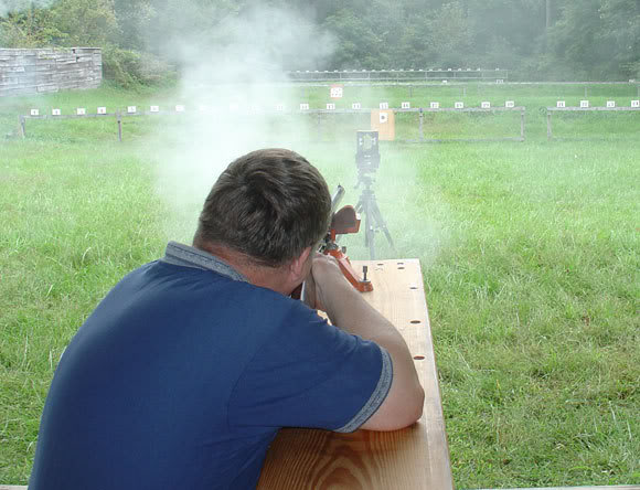
    I brought my testing set-up into the basement . My garage is heated but I’d rather not run temps up and down because of some old cars. Will if I have to. I will be testing infrared gates and beginning to figure out the methods.

    I have to thank an ALR guy for a real stroke of luck. He offered me a sample of colonial period oil to include in the tests. That gives us a chance to include what I expect is the best of colonial lubes available.


    Progress has been slow today. I spent my time solving problems with infrared gates. They have always been troublesome, but today static electricity in my dry basement and the sensitivity adjustments have taken too much time. A potentiometer may need to be replaced. There are a few fixes to try before I resort to that though. During teh afternoon I did get a dry run done using Rem oil on the lock. Numbers ran from .0160 to .0220 seconds. This won’t be used as a bench mark because the sensitivity may change the results. So, nothing final here, just some slow progress.

    I finally solved the gate sensitivity today. I replaced the two potentiometers on the interface board. These seem to adjust smoothly and give me much more control of the gate sensitivity. I did a short test and feel I’m ready to begin the testing.

    The cleaning method is my next problem. My plan is to do a three stage cleaning. First the lock goes into warm water with a little dish soap added and be scrubbed. Next into rinse water and blown dry. Lastly I’ll use acetone or alcohol to do a final rinse and blow dry. That should leave the lock absolutely lube free.

    Beginning each set of trials and after applying lube, I’ll snap the lock a couple of times before timing the first trial. Hope things go well.

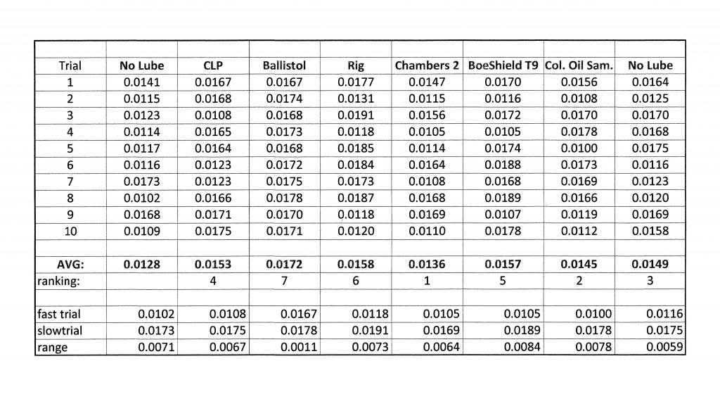
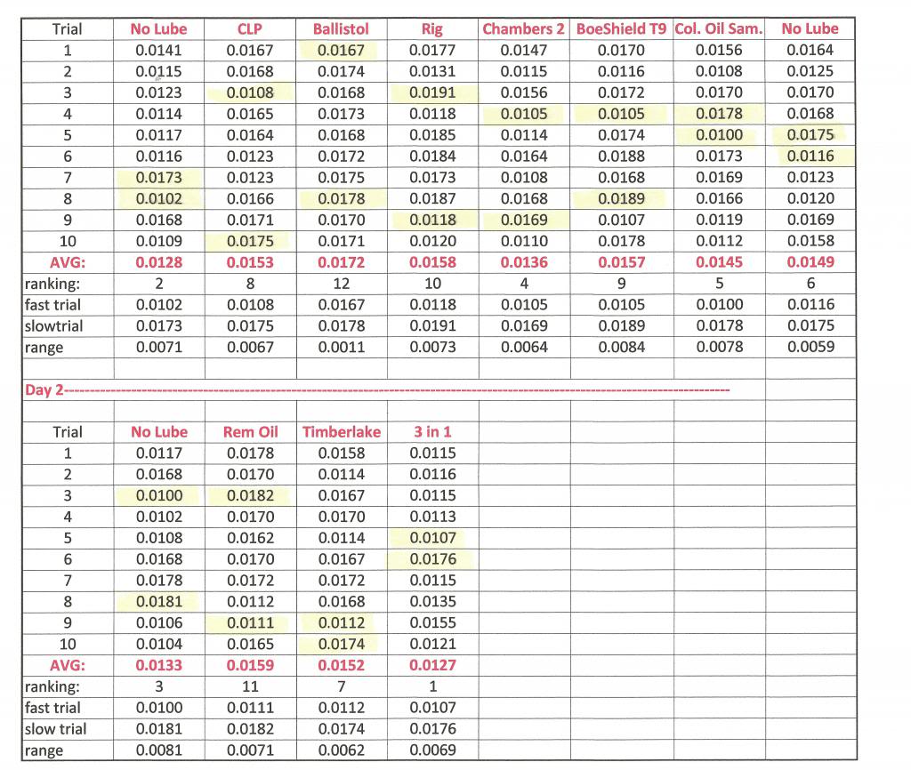
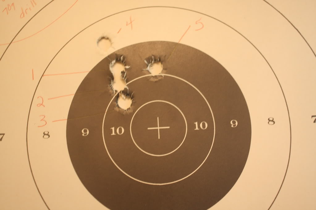
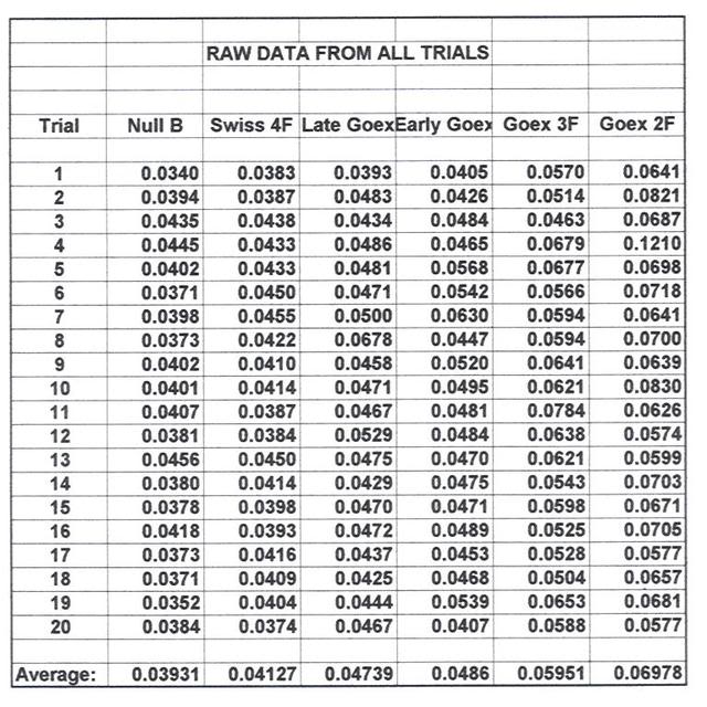
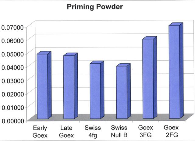
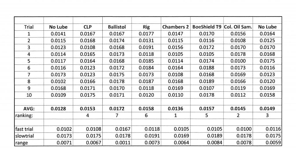
    Today I tested six lubes against a trial with no lube at all. My gut said that the lubed tests would be pretty close with the no lube slower. This was not the case, however. The no lube trial averaged in the middle of the lubed scores. Below are the lubes in the order they finished with their average for 10 trials:

    A few comments need to be made about these scores and lubes. First it was very hard to clean the lube off between trials. I had to wash the lock carefully in alcohol. This last step had to be done more than once in some cases. I timed the no lube first and realized I didn’t wash it thoroughly enough, and had to toss the times. If I used those numbers, no lube would have been in first place. Cleaning definitely is the crucial step here.


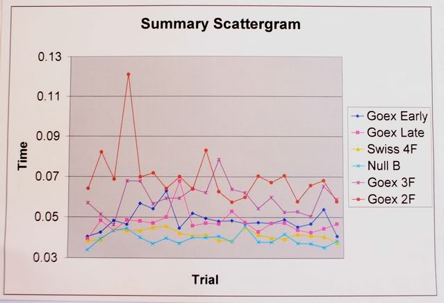
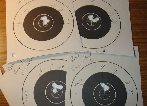
    The trials are in the order of testing left to right. The “no lube” in the left column is the one in which I felt I did not clean well enough to use. Instead I decided to retest at the end. That trial is on the far right. The times within each trial are in order from top to bottom. This is probably not as significant as it would be if a flint edge was used. The range within each trial was wider than I expected. The exception is in the Ballistol group where the range is significantly smaller than the rest. It was the slowest in the group also.


    The infrared gates worked better than before I swapped the parts on the board. I got a few scores out of range, but not many.

    The Chambers product was a 2 part lube. A white grease was used between main spring and tumbler and also on the frizzen spring. A thin oil was used on the rotating parts. The white grease was very hard to clean off after this test.

    The “Colonial” oil sample was the only sample that would be historically correct.

    The individual times in each set were more widely spread than I was expecting. The averages were in the ball park with earlier timing. The mechanical times for this same lock, published in the JHAT vol IV, was .0151 seconds IIRC. .

    I have a number of other lubes to try, however my cold wore me out and I stopped with these today. I will probably try to get a few more done, but after today I think I know how it will turn out. (I didn’t do my favorite which is Rem Oil.) I’ll continue to look at the numbers for any trends.

    I want to continue to mull all this over, but I think the differences are statistically insignificant. The ranges of trials were too wide to be decisive. In fact the narrowest range was for Ballistol, the slowest average. This would be easier to see if you could see the group of scores for each lube. I’ll try to see to that.

    I do like Jim’s lube combination. The lube for sliding surfaces makes sense. Between shooting sessions, I would use a lube based on its rust prevention. I better let it go for now. This needs more thought.

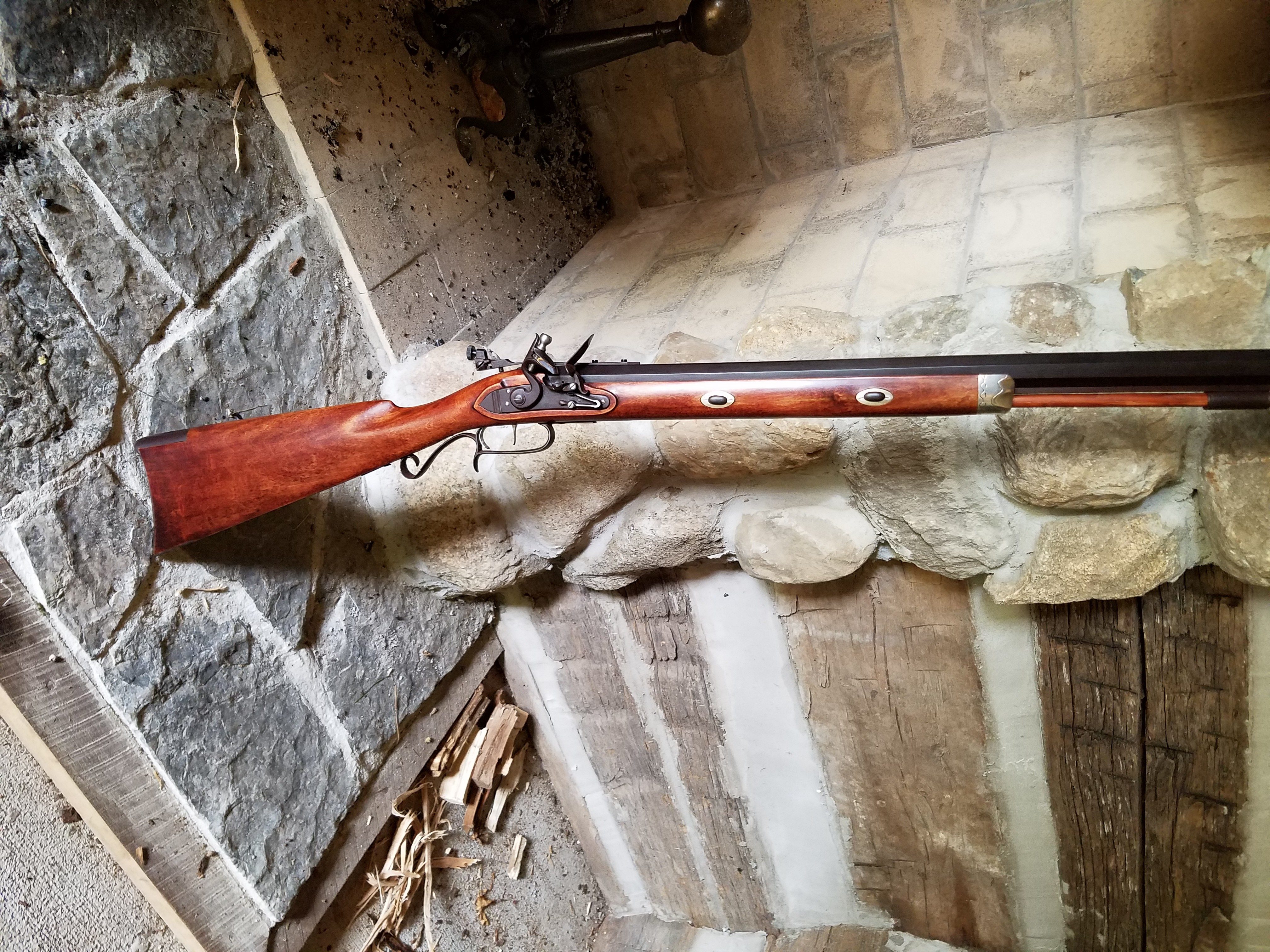
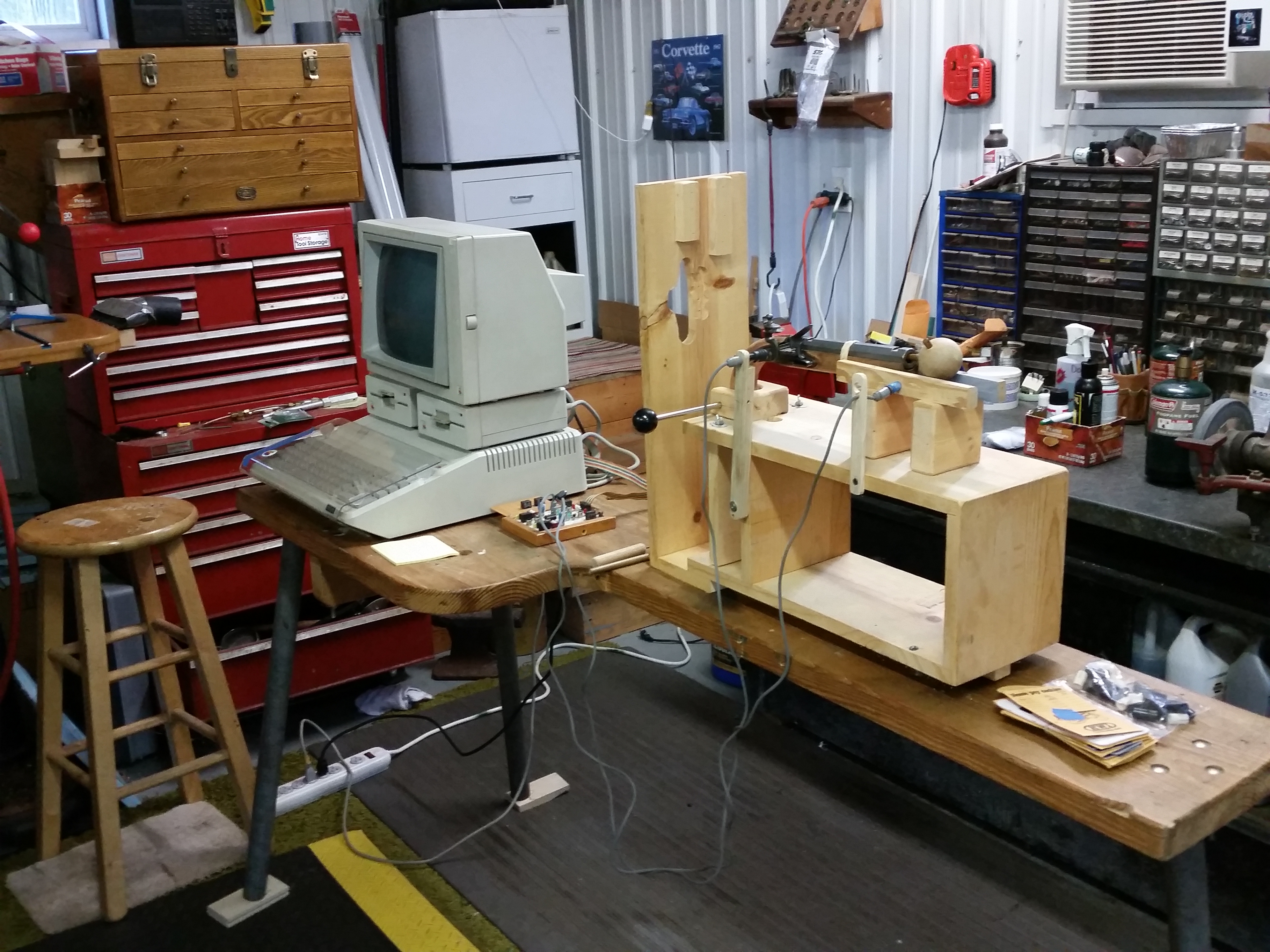
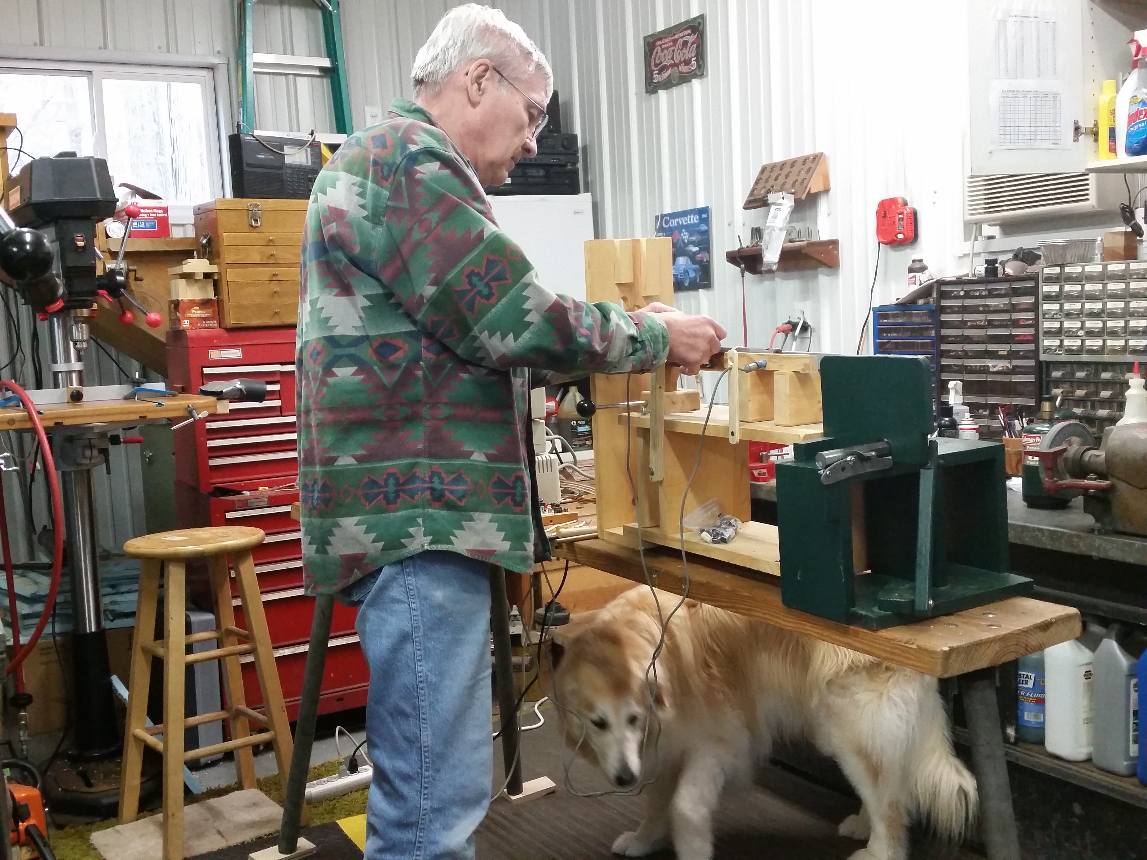
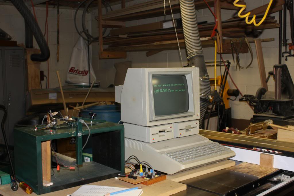
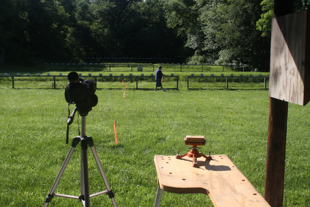
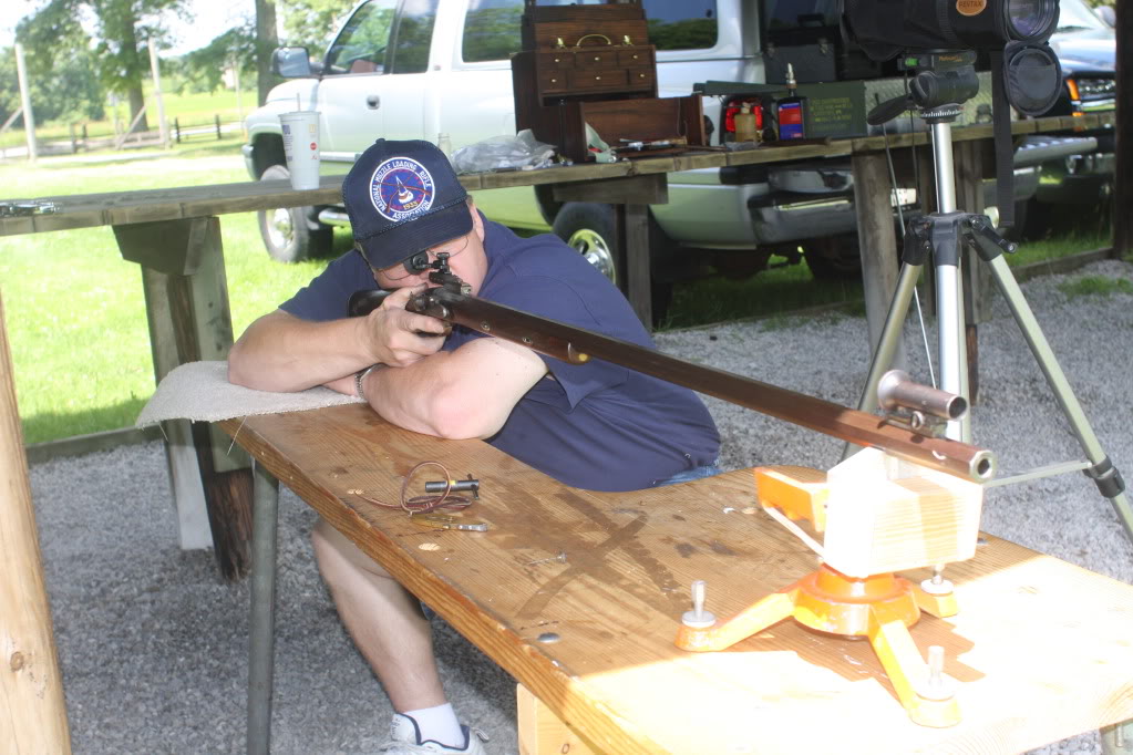
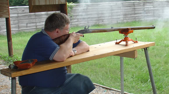
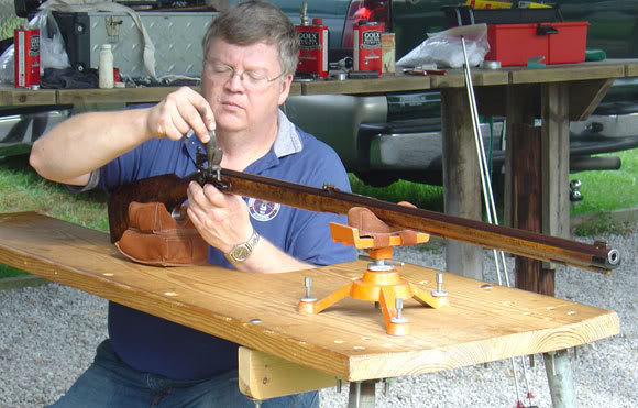
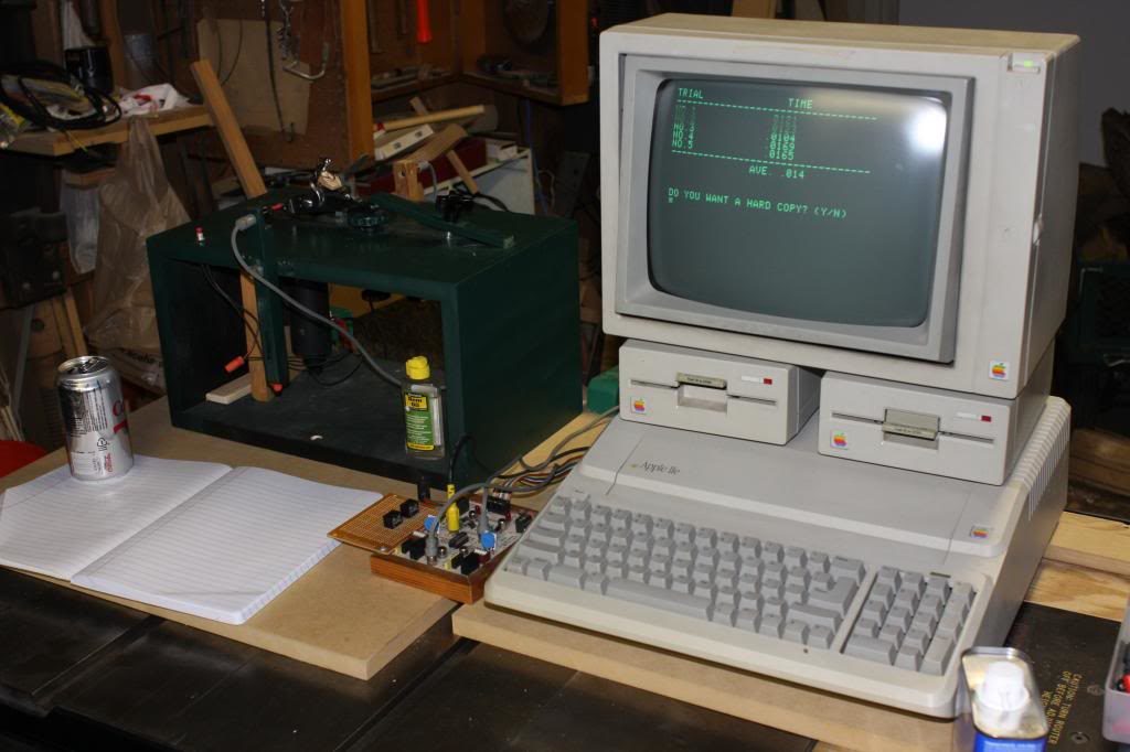
    Here are a few photos of the setup and the spreadsheet that includes all the trials:
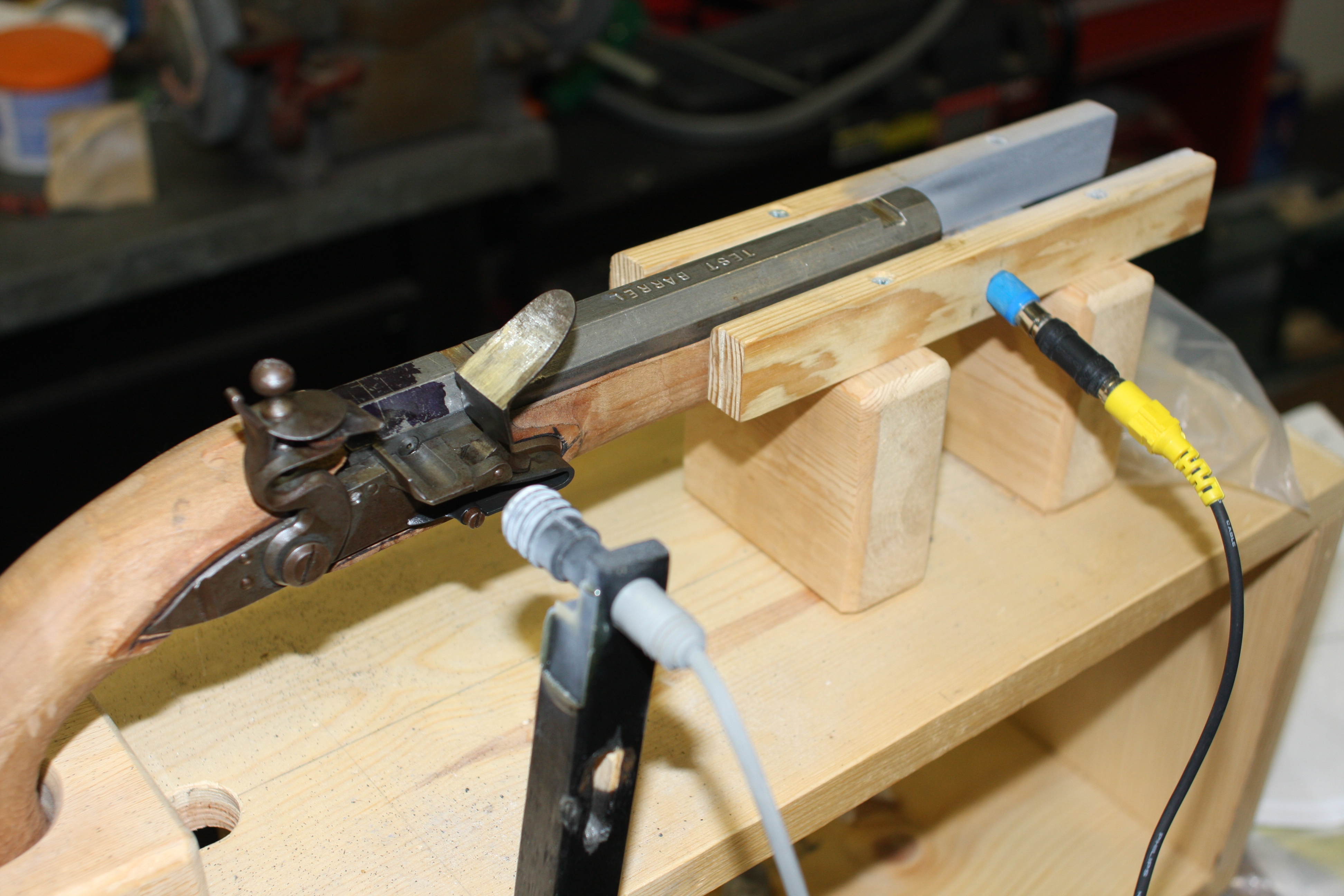
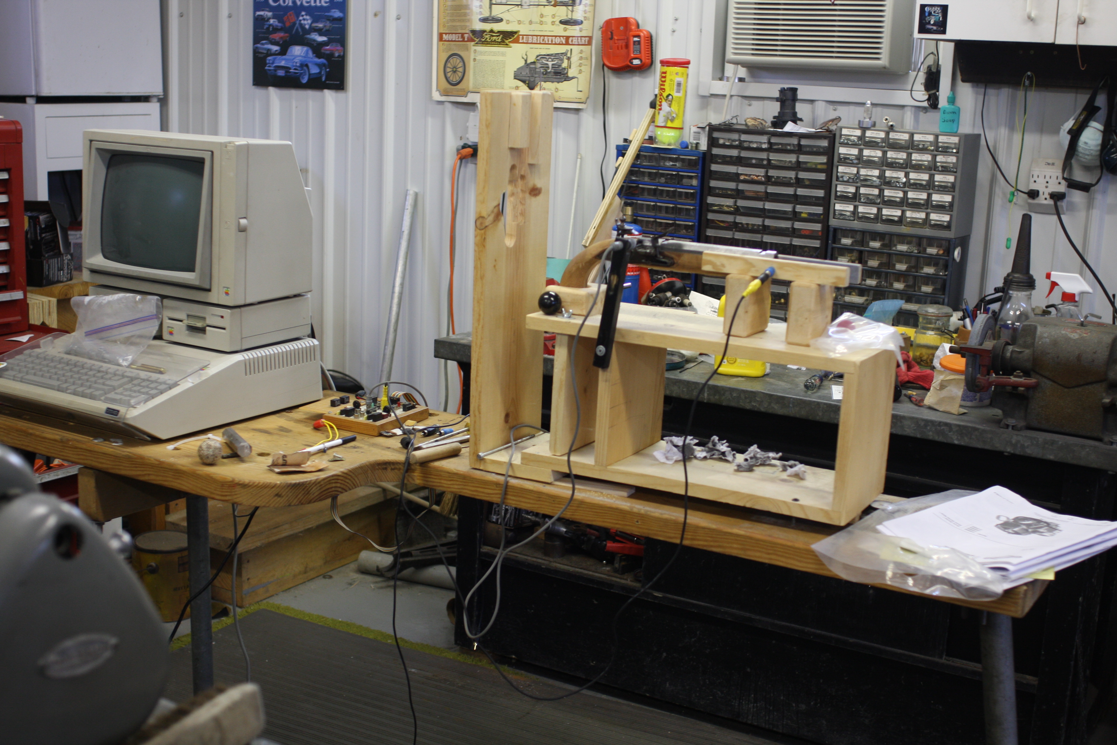
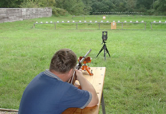
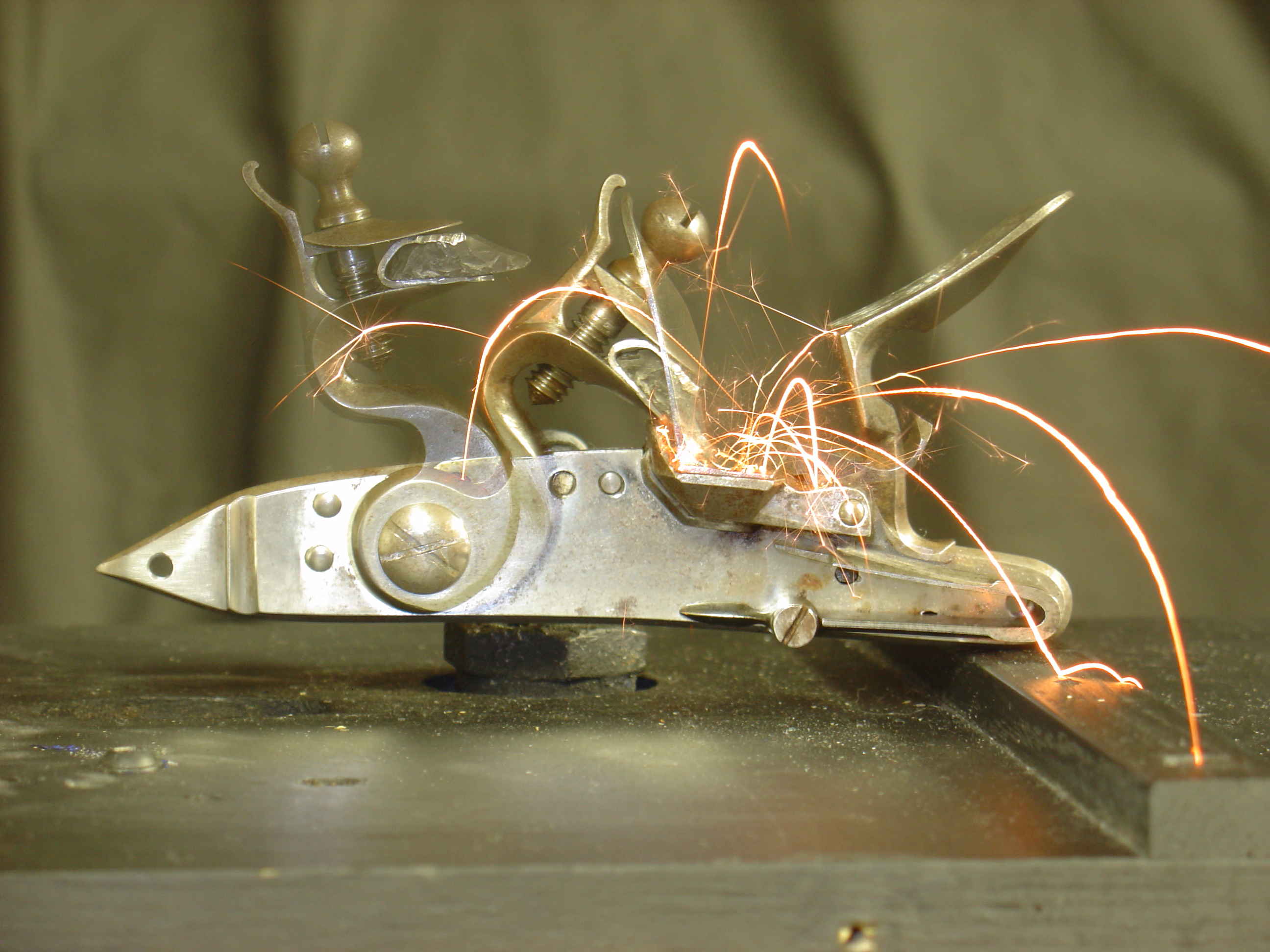
    This is the overall setup I’m using.


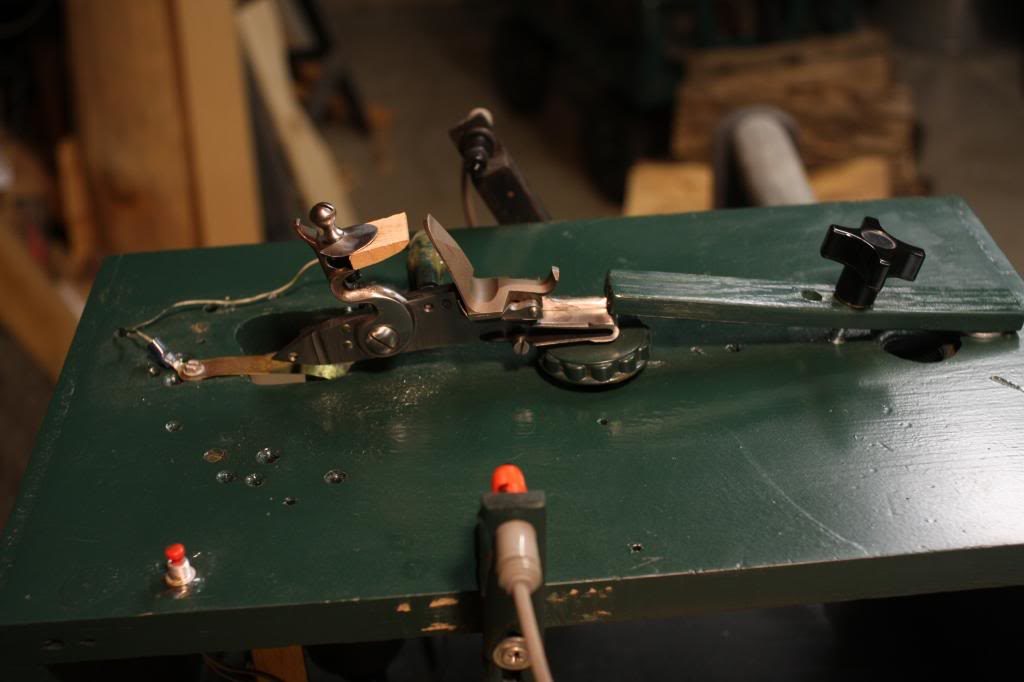
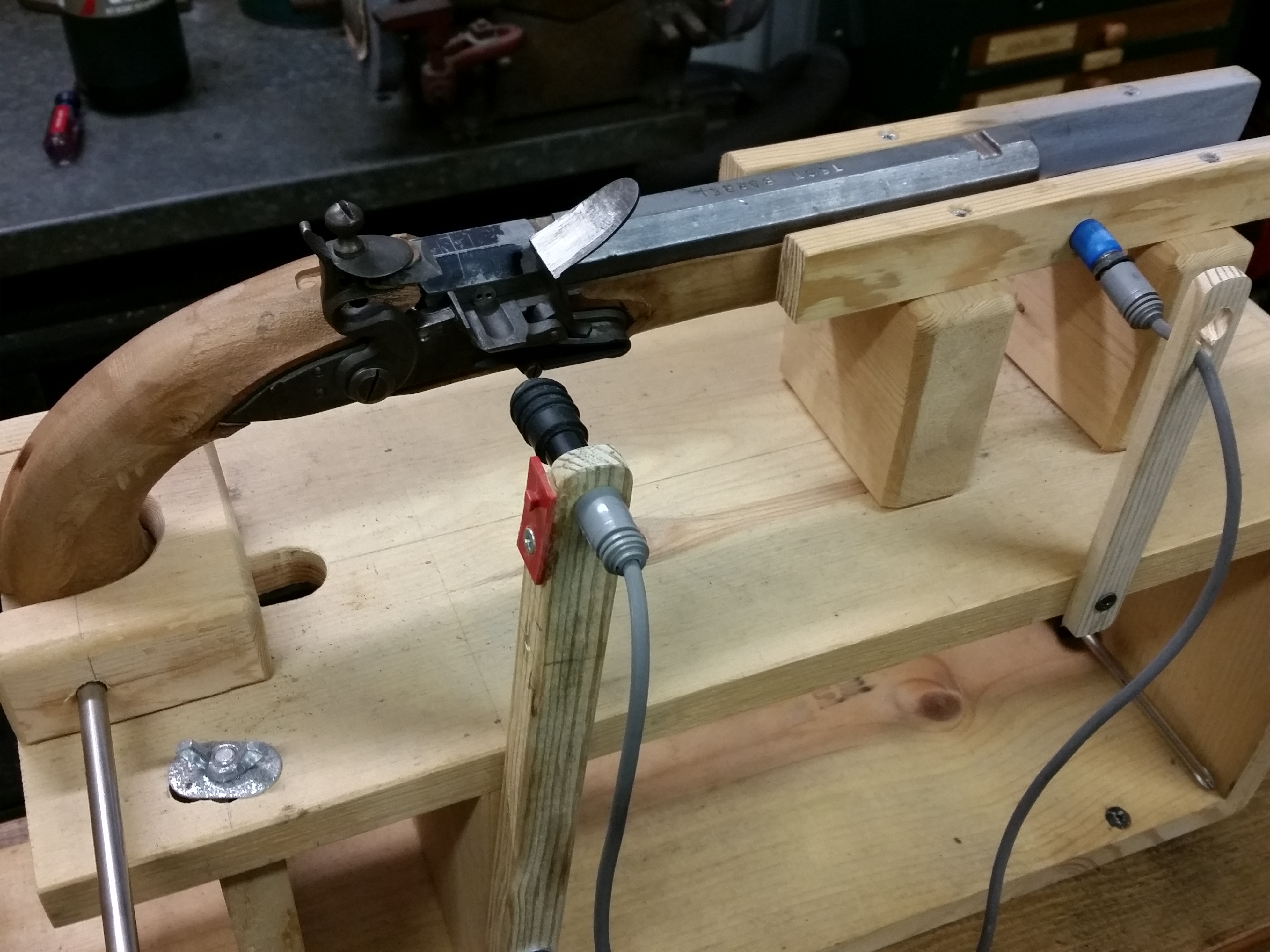
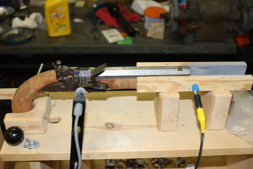
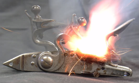
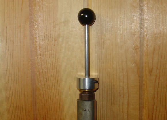
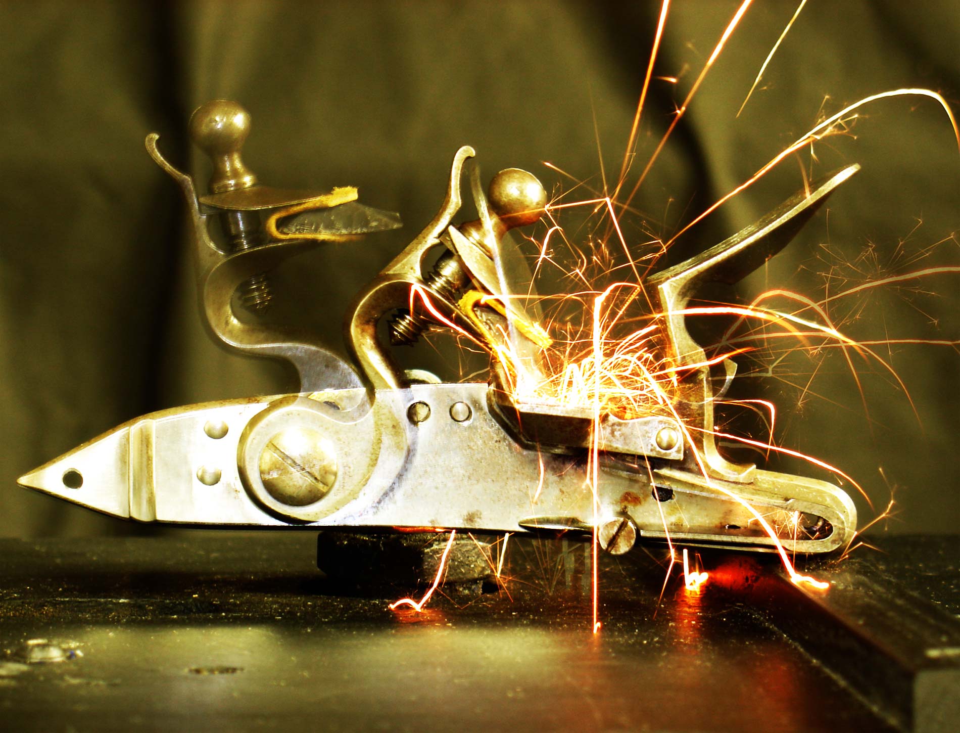
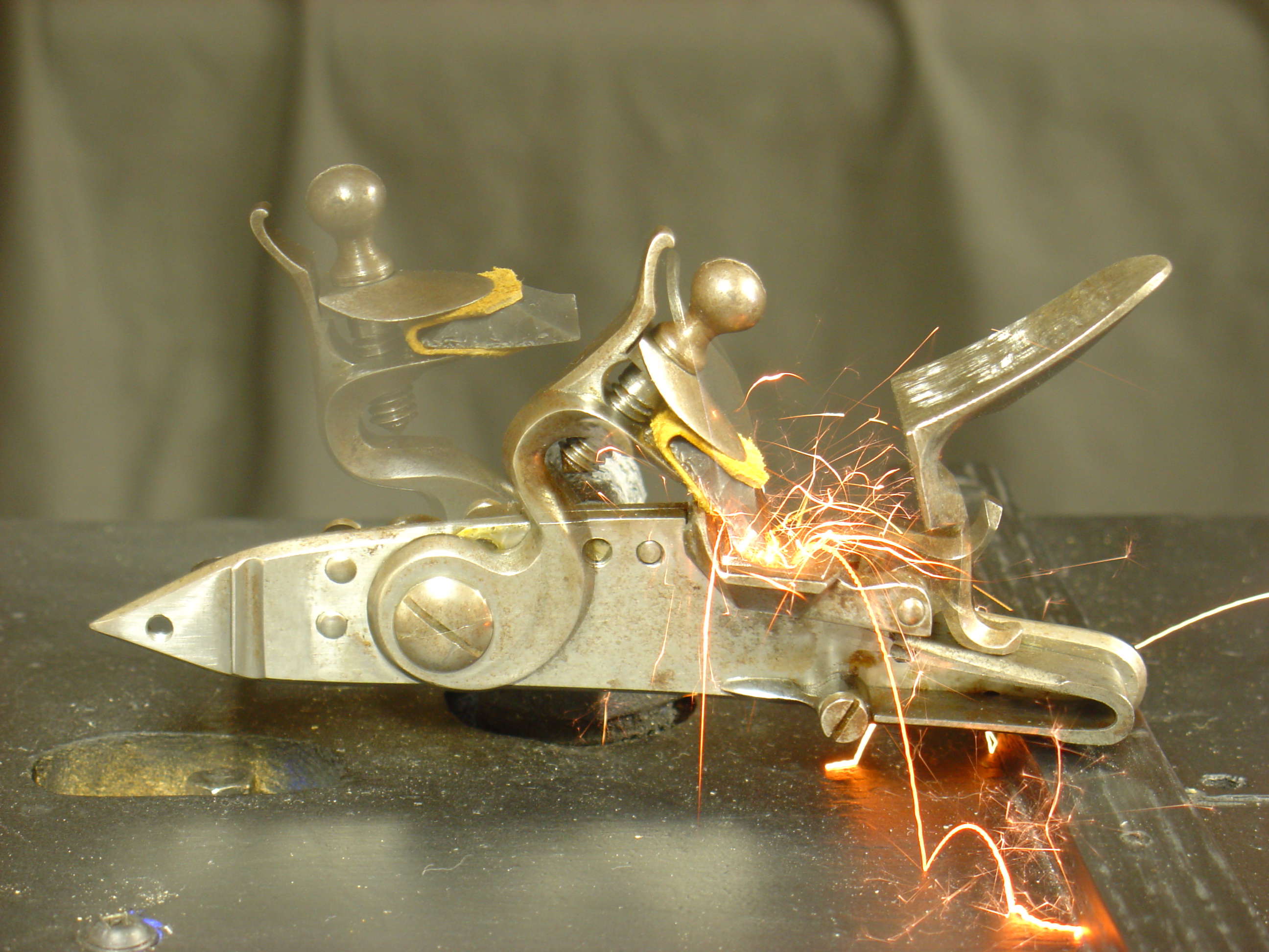
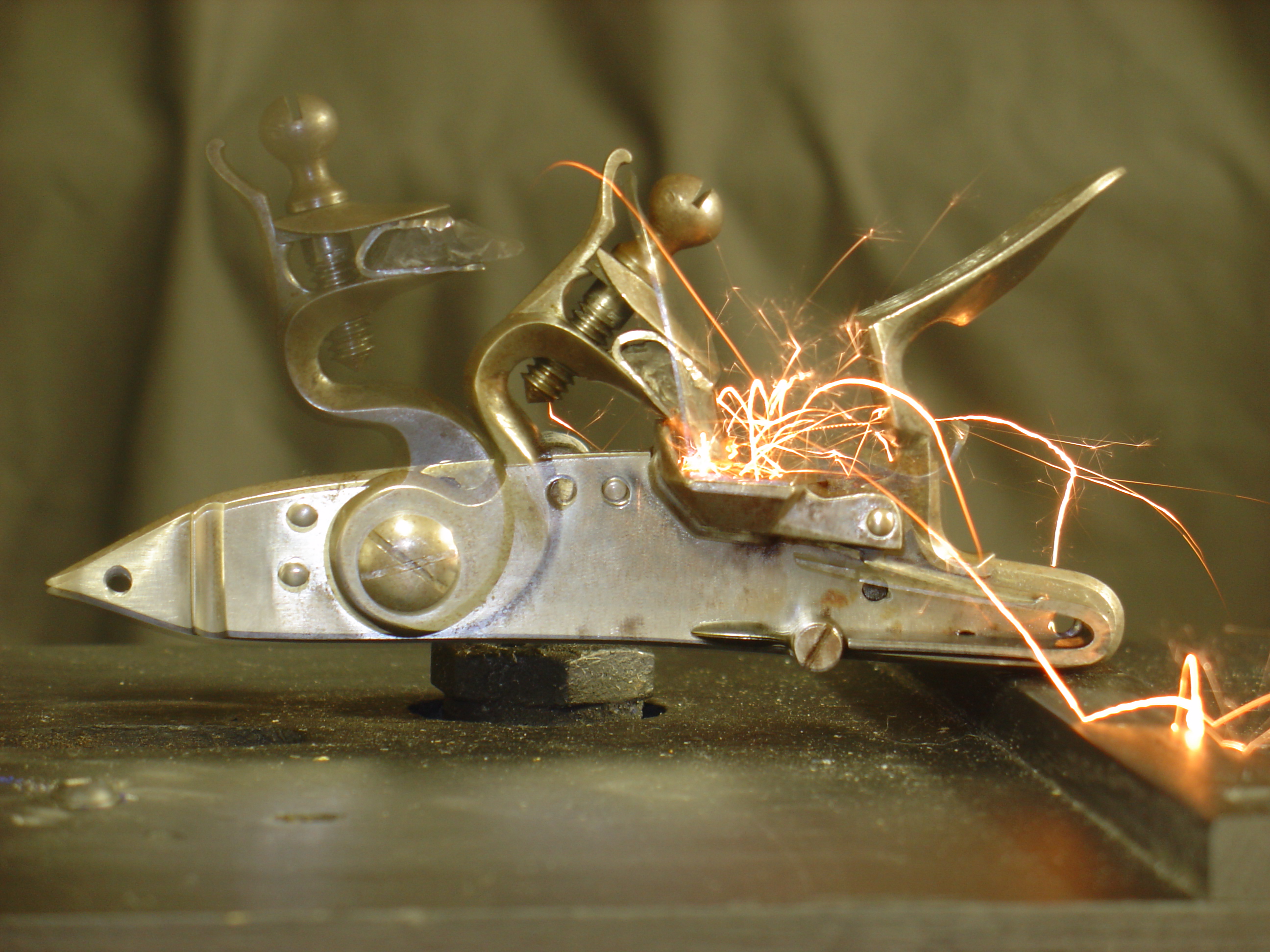
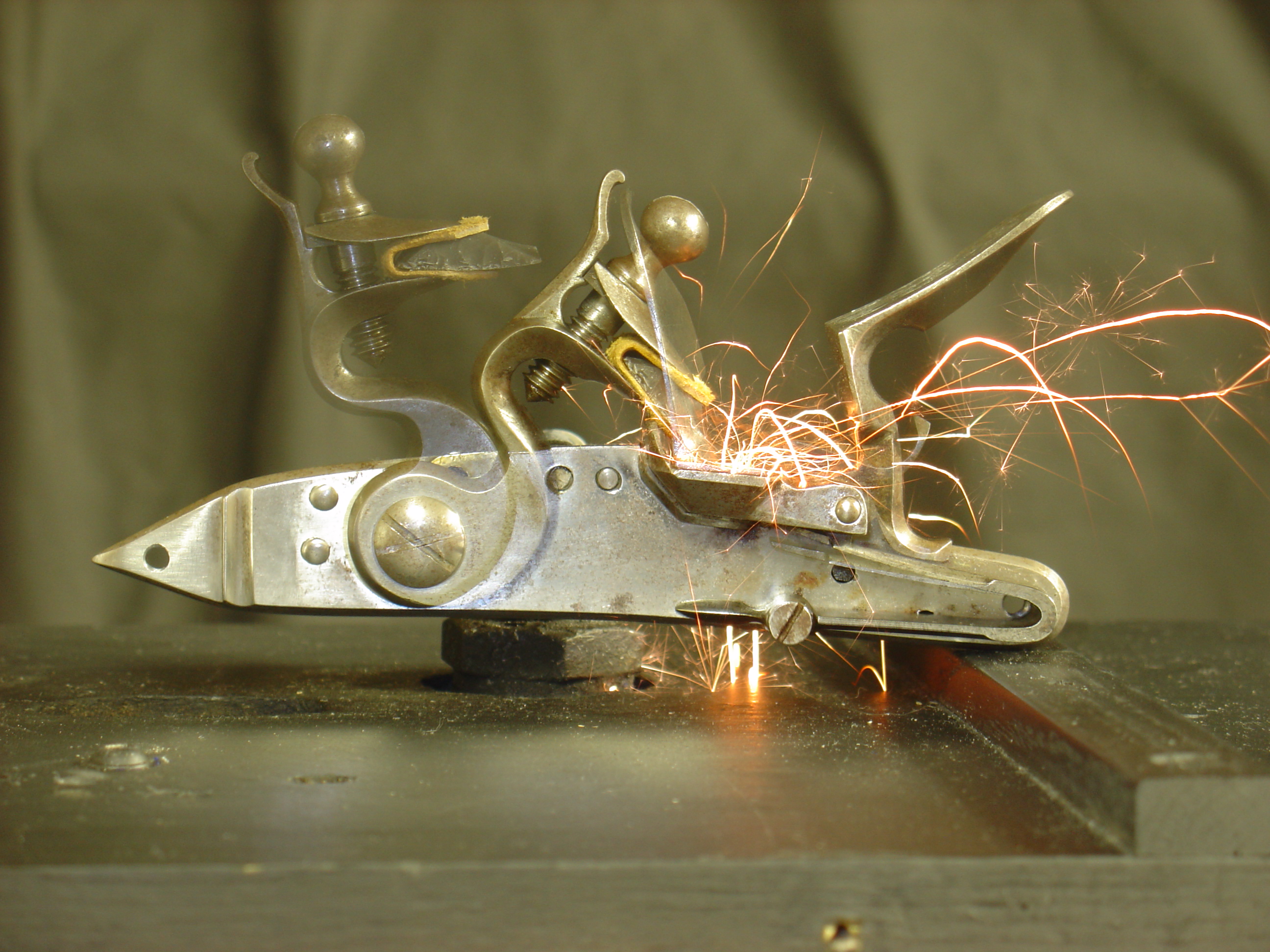
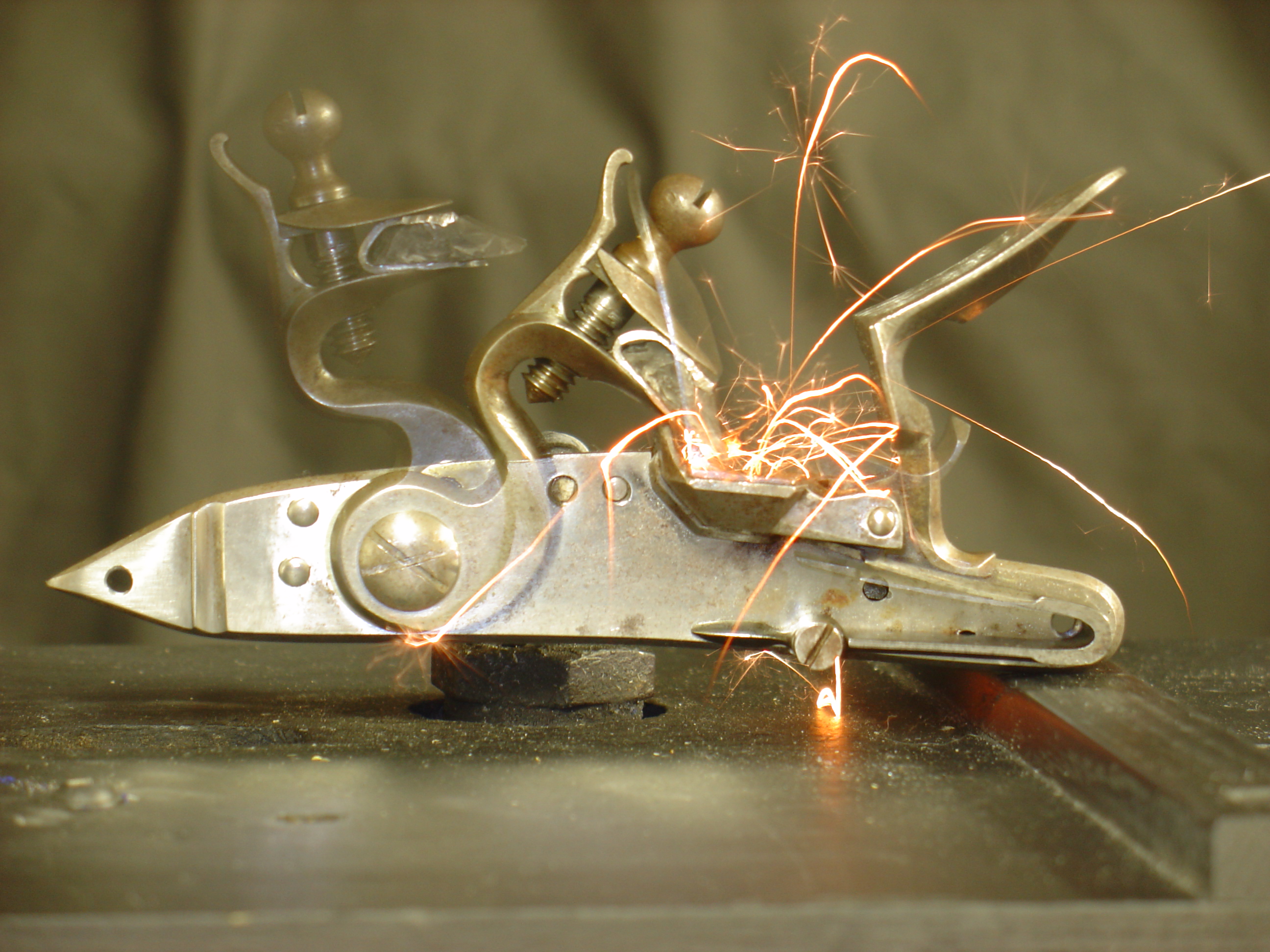
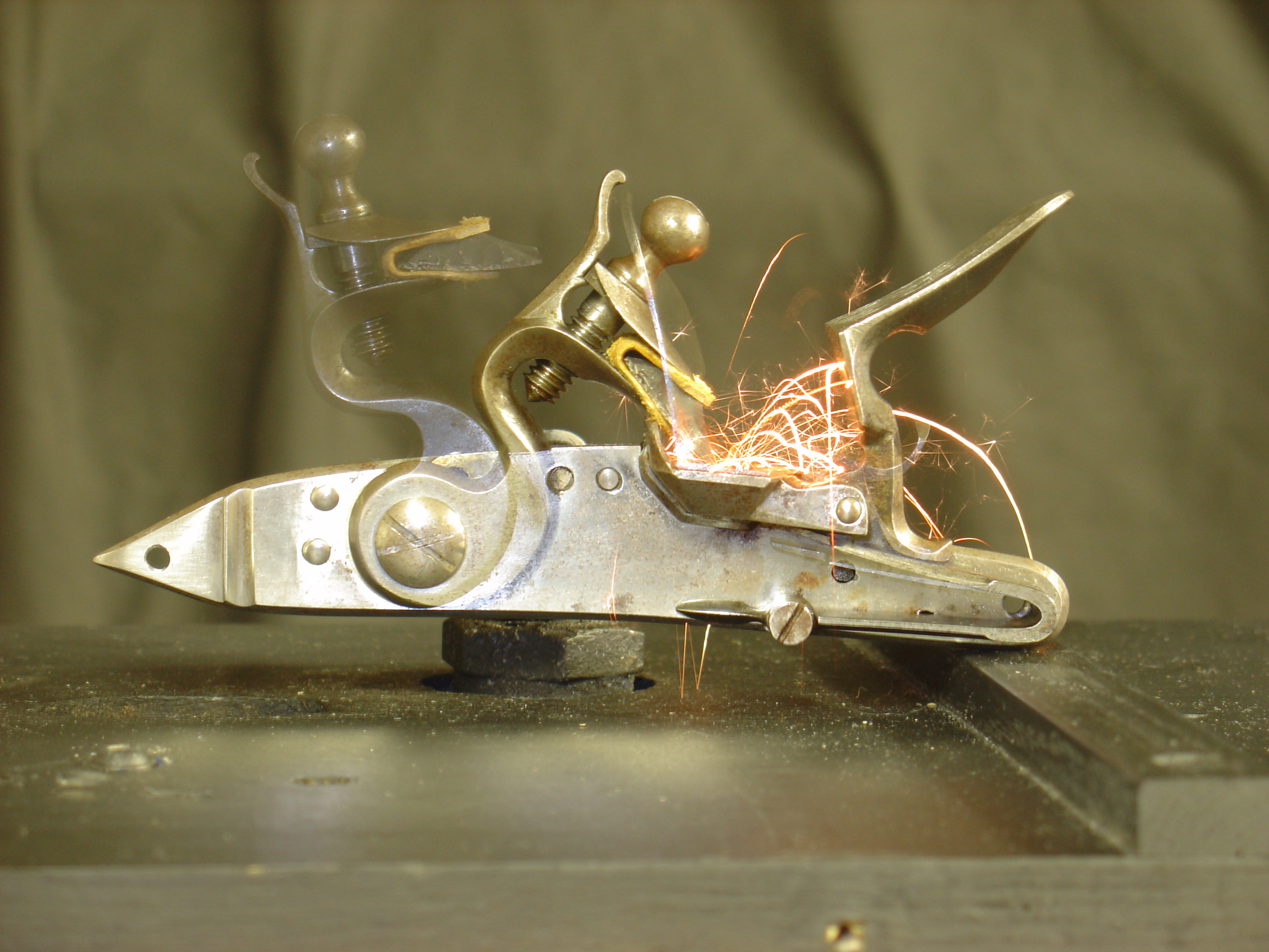
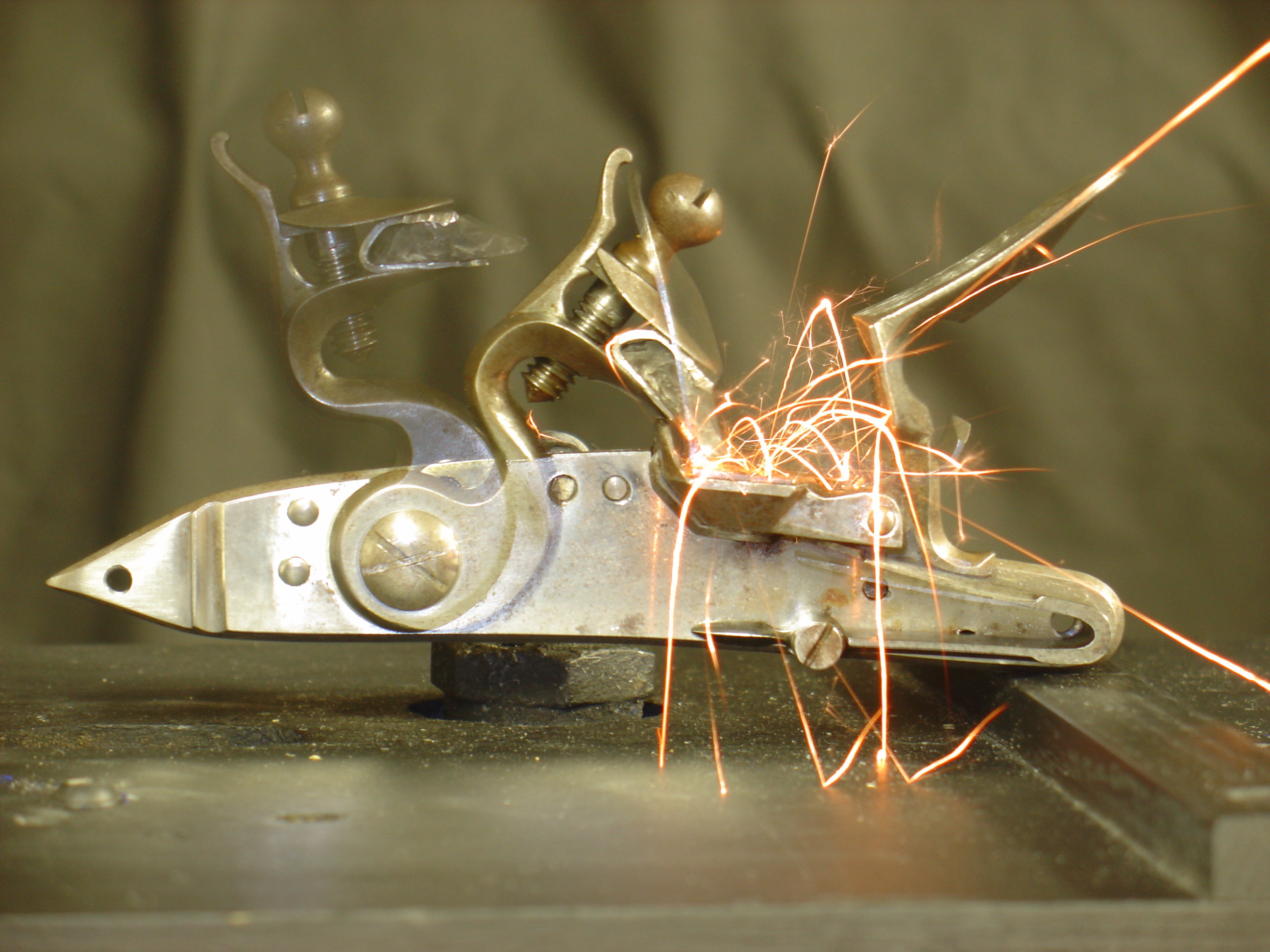
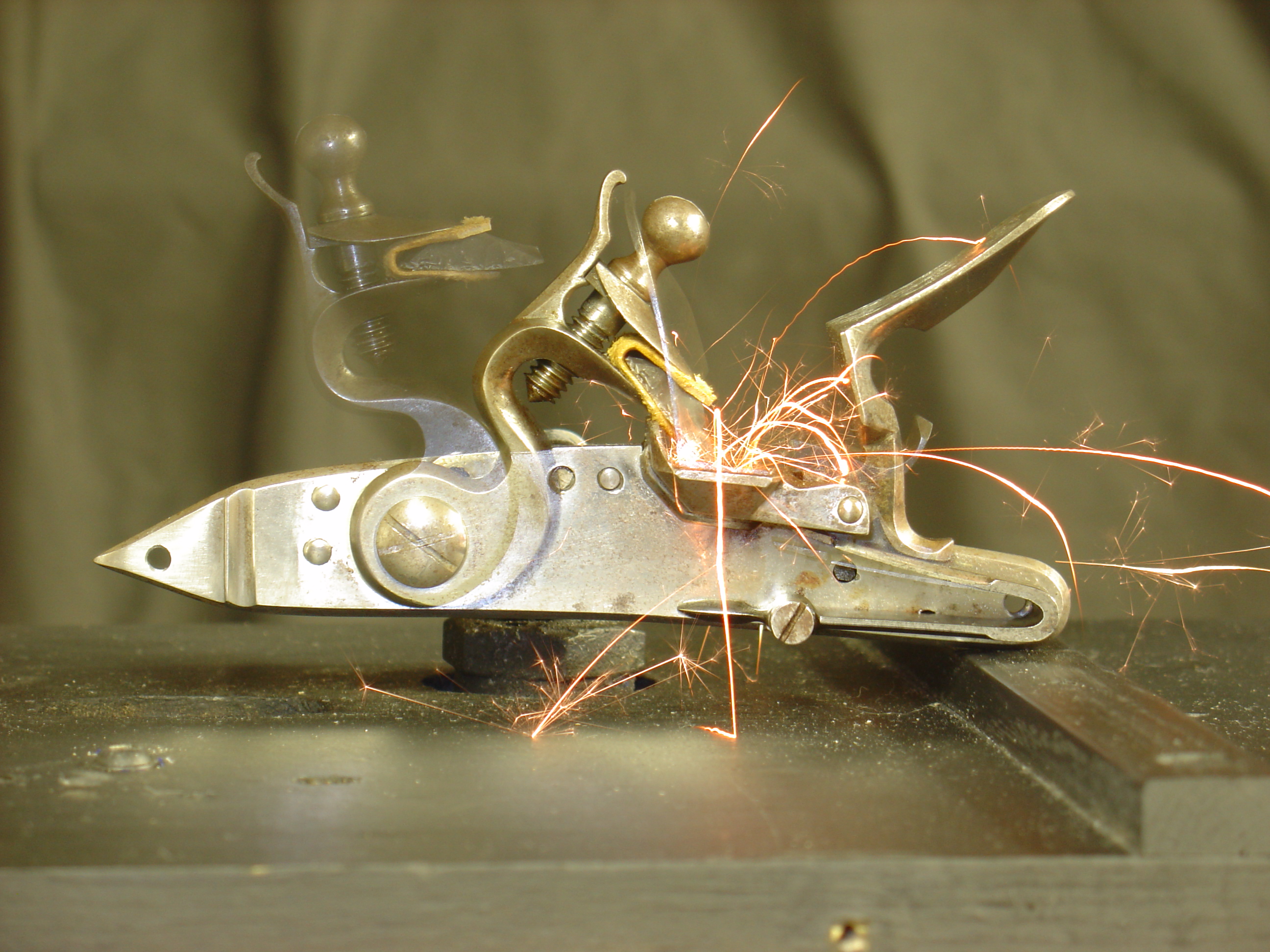
    This pic shows the fixture with the Siler installed. The orange RCA plug in the forground holds the led emiter, while in the background is the detector (black). The infrared beam is positioned right above the frizzen. When the frizzen rises, the beam is broken.


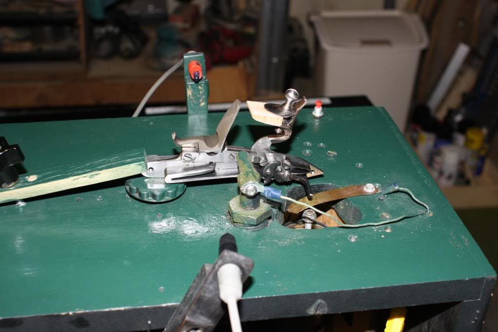
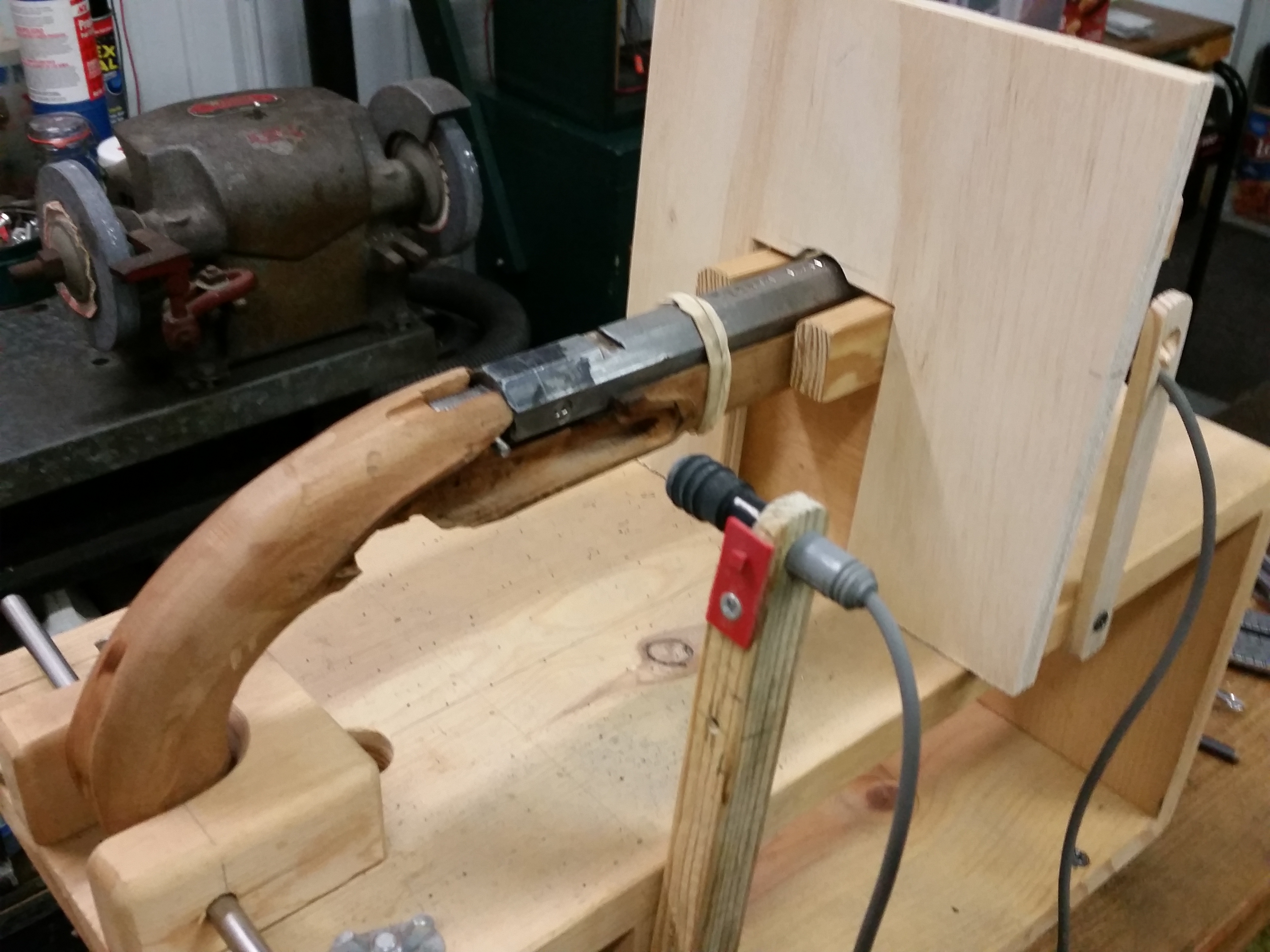
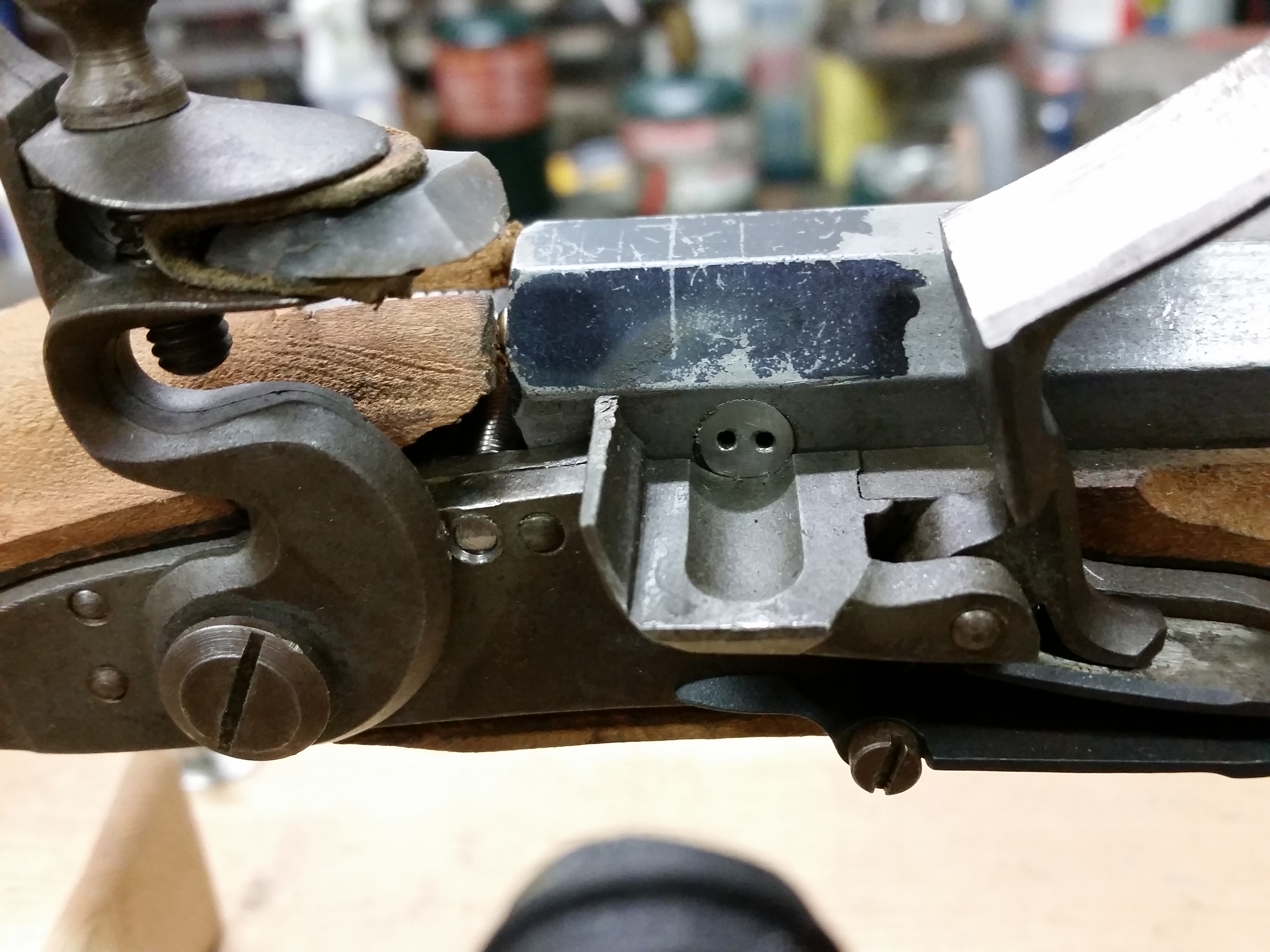
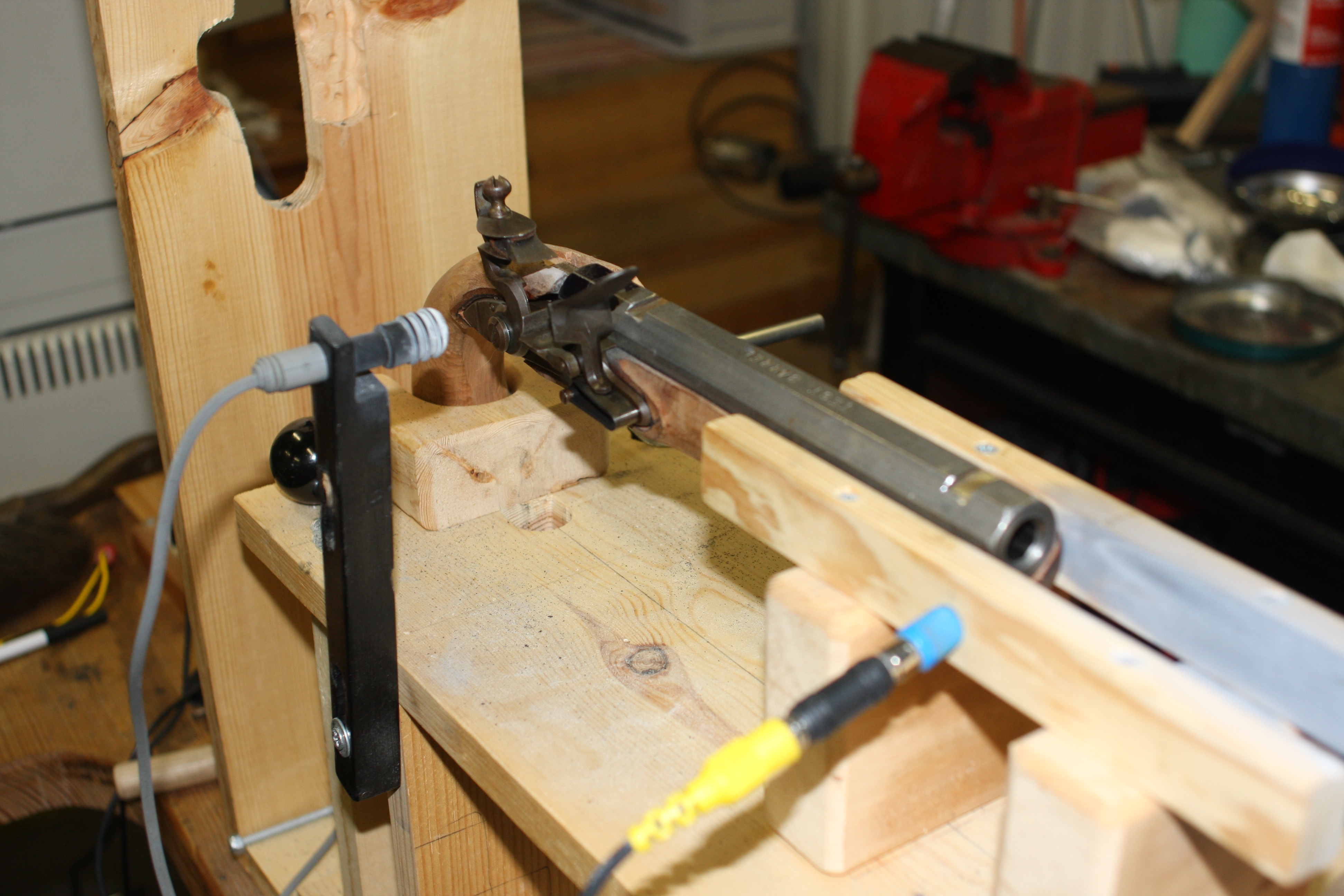
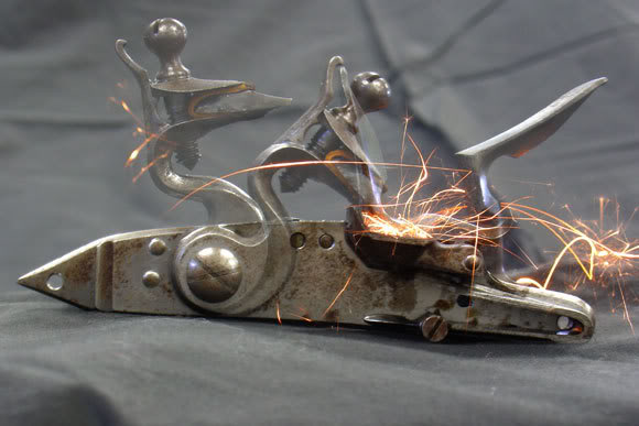
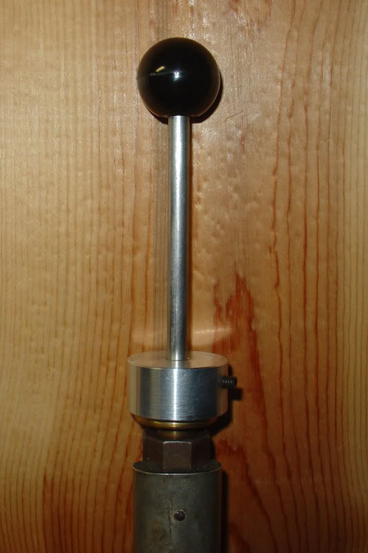
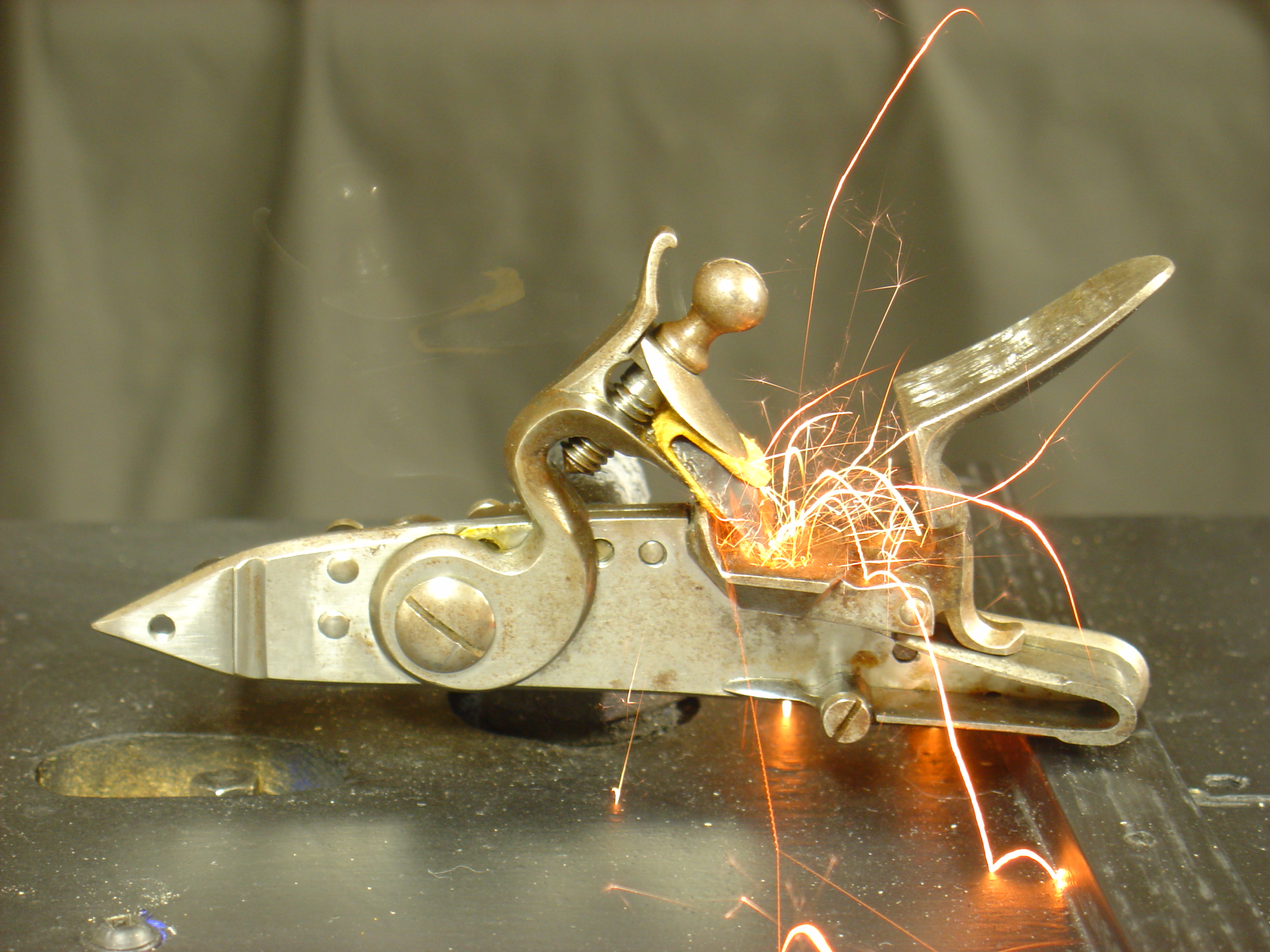
    This shows the fixture from the back. Now the detector is in the forground. Here you can see the plunger below the sear with a thin brass blade between. When the plunger pushes the brass against the sear, the contact is made that starts time.


    This last pic is the interface. The glowing green led lets me know that the infrared beam is not broken.

    The mention of ultrasonic cleaning sounds interesting. Using brake parts cleaner sounds good too. Would the parts cleaner leave a coating that could be removed by alcohol? BTW, I figured alcohol would leave no coating. Hope that’s right. I should mention that I would use compressed air on the lock until no alcohol was left. I was surprised to see alcohol coming out of the sear and sear spring screws on the front of the lock plate.

    The overlap is one reason these are IMHO statistically insignificant. As far as lube not removed, I think I got that solved after the first cleaning. After that I used plenty of alcohol and used compressed air until no alcohol came out – even from screw threads.

    The real surprise was the substantial reduction in range shown by the Ballistol. While it had the slowest average, the lock was far more consistent with this lube. Methodology was the same throughout, so I have no explanation for Ballistol’s consistency.

    I need to think about what material is the last step in the rinse before re-lubing. Is there a better fluid than alcohol? Other than ether (starter fluid) does anything leave NO residue? I feel that key to a clean lock means a final rinse with nothing left, including a residue of its own. Any ideas better than alcohol or ether?

    The problem with a trace of oil in the compressed air was a possibility I hadn’t considered. As you probably read I moved my stuff from my garage into my basement when I didn’t need to use priming powder and flint. My garage air would have been filtered, but my basement compressor lacks a filter. I can rule out the problem by leaving the stuff in the basement but doing the lock cleaning in the garage. It adds a bit of time to the process, but lock-cleaning takes more time than running the tests anyway.

    If I had a real lab behind me, some of those methods would probably be the answer. Since I’m a retired teacher working from my basement, I may have to settle on the best solvents readily available. I used alcohol as you know, but also have acetone and ether (starter fluid). One of my friends may have a couple more. I’ll give this more thought over the weekend and pick the brains of a couple local engineer friends.

    In looking over the stats I am beginning to doubt what I know so far. Numbers within a trial vary so widely, I am beginning to look for an unknown variable. The problem is that solvents and methodology used so far have been the same throughout the tests. Is there a variable that widens the data that we haven’t anticipated. Just thinking. . .

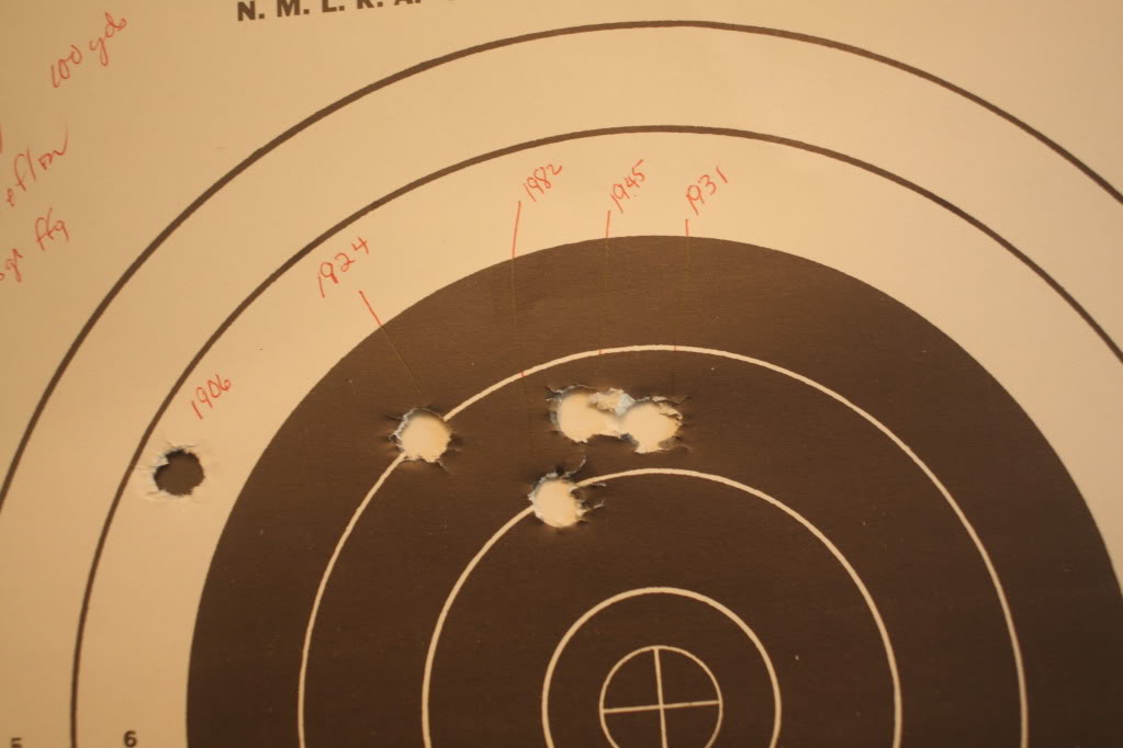
    Today I ran tests on more lubes plus another run of no lube. I have more photos to add but photobucket freezes every time I try to add another photo. The chart below contains both day’s work with day 2 at the bottom. I decided to leave in all the no lube groups when I saw that today’s was in about the same time category. I also highlighted the fast and slow time in each group. In a couple of cases the fast time and the slow time were next to each other in sequence. The ranking now includes all the trials from both days.


    I changed cleaning methodology today. First I’m using filtered conpressed air to rule out the possibility of trace amounts of oil when drying the lock. Also, after using warm soapy water and a tooth brush on the lock, I used a series of 4 baths in acetone. I chose acetone over MEK because it evaporates more quickly. The purpose of the 4 baths was explained in an earlier post so I won’t go into that again. But I have confidence that trace amounts of oil are not involved in the testing.

    After 2 days of timing, I feel that we will not find a super lube that is head and shoulders above the rest. Since the lock seemed faster with no lube, perhaps the trick is how to apply a very small amount. The containers that the oil comes in may play a part in this.

    The wide range of times, especially overlapping as they do, make me conclude that lube quality does not influence the mechanical time of the lock. The question then is why not. My gut says that the very small amount of rotation is prehaps too brief to accurate measure the effect of lube. If we were dealing with a machine that rotated a number of revolutions, maybe we could see the difference. I don’t know.

    If we do not choose a lube for speed, my choice would be to choose a lube for it’s ability to increase the life of the lock. I asked this question to Jim at Friendship. His answer was that he would choose a lube with the longevity of the lock in mind. My gut says we should too.


  • Filled Vent Test – Is it Slower?

    Filled Vent Test – Is it Slower?

    Filling a flintlock touch hole with priming powder causes a slower ignition. The pan fire has to burn through instead of flash through the vent. Is this “fuse effect” true? Can the difference be measured? Are the “hang fires” experienced by black powder shooters caused by something else? Reporting the answers to these questions is the purpose in this article.

    The purpose of this test was to see if there was a measurable delay in ignition when a straight cylinder vent was filled with priming powder. (We did not deal with vent liners in this test.) For the purpose of this experiment I will define this “fuse effect” as an ignition delay caused by the priming powder having to burn its way through the vent to ignite the main charge instead of “flashing” through the vent. I’m personally not fond of the term because it implies that we know what caused the delay. I like the term “hang fire” because it does not suggest a cause.

    The test was set up using a fixture we used earlier to time lock ignition speeds. We used a “pistol” with a barrel stub, small Siler lock, and my computer with photo cells “looking” at the pan and barrel muzzle. The barrel is loaded with 30 gr 3fg and a sabot to hold powder in place. The pan is primed, and ignited with a red hot wire to eliminate lock variables. Between firings, the barrel is wiped with two patches, a vent pick used, and compressed air is blown through the vent to insure that the vent is clean. The pan is primed with Null B close to the barrel. The only difference between the two test phases was that the vent was completely empty in one, while in the other, we picked priming powder into the vent until no more would go in.


    The barrel used was octagon 7/8” across the flats and was .45 caliber. It had a flat flint-type breech. The vent was a straight cylinder with a 1/16” diameter approximately .21 inches in length. Time starts when the pan photo cell is triggered and stops when the barrel photo cell is triggered. Thus barrel time is included in this test, however this obviously the same for both vent conditions.


    We recorded 5 trials for each vent condition. The average time for the clean, empty vent was .028 seconds. The filled vent average was .031 seconds. As you would expect, the slowest time we recorded was in the filled vent phase (.0363). However the fastest time of the day was also in the filled vent phase (.0233). (We also did a single clean vent trial where we banked the prime away from the vent and recorded at time of .067 – more than two times slower than the clean vent average.)

    These averages are quite close together. We expected a larger difference because our ears tell us a hang fire has taken place. And, here is the most unusual finding. The fastest time (.0233) we recorded sounded as if it was a hang fire. The slowest time (.0363) recorded sounded like a sharp crack – no hang fire – sounded like a .22 rim fire. This reinforces a belief I have long held that our eyes and ears are terrible tools for judging flint events.

    This all makes me wonder what we are really hearing. Maybe our ears send us false information. Consider this: You are three shots into a target and have 3 tens. You shoot the 4th shot and it’s a nine. Sounded fast, but you think it was just you. You shoot the 5th shot, and it has an audible hang. You look through the scope, and no. 5 is back in the 10 ring. Maybe the fourth shot was slow, the fifth shot was fast, and your ears are at fault. With what we learned here, it could be possible. I truly don’t know the answer. Sometimes experiments leave you with more questions than answers. I do know that I trust my ears less than the numbers.

    There are so many variables that can cause delays that in most cases it can be impossible to rule out all but one. That was the purpose in our experiment. We wanted to put a number on the amount of delay, if any, caused by packing a cylinder vent with priming powder.

    The delays we found were measurable but not large enough to account for the delays we have measured in pan ignition – where the variables were flint edges, priming, particle size, and location of the prime in the pan. I have measured far larger time variations caused by these variations. The other big factor is the delay caused by fouling in the vent. A vent full of priming is one thing, but a vent filled with fouling is quite another. Besides causing huge hang fires, I believe fouled vents are the flint shooter’s biggest cause of failures to fire.

    If I were to list the top causes for delays based on my testing they would be:

    1. Lack of good spark production from good flint edge

    2. Improper priming location in the pan with good priming powder

    3. Vent not absolutely clear of fouling.

    (A clean vent filled with prime is not a major cause IMHO.)


  • ITX Non-Lead Field Test for Accuracy

    ITX Non-Lead Field Test for Accuracy

    Do you live in a lead-free hunting zone? Are there alternatives for the traditional muzzleloading hunter? BlackPowderMag examines one possibility.

    Recently I received a quantity of ITX non-lead balls made to be fired in a muzzleloading rifle. The maker is Continuous Metal Technologies Inc located in Ridgeway PA. Brad Clinton is the contact person. The company produces non-lead projectiles for hunting applications. If, for a variety of reasons, hunting with lead becomes unlawful, these products may prove to be a viable alternative.


    You can see a belt running around the ball. This ball measured .487 when not measuring the belt. Around the belt it measured .002″ larger. We seated the ball with the belt level – (with the belt thought of as the equator, the North pole was up). We speculate that if the belt went in slanted, it might be possible to damage a land.

    This week Steve Chapman and I worked on testing the non-lead ball in a .50 caliber muzzleloader. Two samples were available: .487 and .490. We planned to test both. The goal was to determine the potential for accuracy with a non-lead patched ball.

    The rifle used was a light bench/x-sticks gun, which Steve used to set a National muzzleloading record. The barrel is made by Green Mountain (1 in 70” twist) and is equipped with target apature sights. When firing the record target Steve used .495 lead balls patched with Teflon. The barrel was wiped between shots.

    Before heading to the range I weighed out the balls. The .487 balls ranged from 156-159 grains. I sorted them into groups to minimize the weight differences. The same was done to the .490s. They weighed 152-155 grains – less than the .487s. I don’t understand this. The weighing was done in the same session on the same surface with the same scales.


    At the range while Steve was sighting in with lead balls, I pushed a .487 patched ball through a barrel stub. We wanted to check on patch cutting with the harder ball. With this barrel stub the ball cut patches with every patch material we tried. We determined the cause to be the crown on the barrel stub. My reason for reporting this is that if your barrel has any tendency to cut patches, this very hard ball will increase this tendency. We saw NO deformation in the ball, no matter how tight a patch we tried.

    We then tried to seat a patched ball into Steve’s target barrel, pull it out by the patch material, and look at the ball and patch. Instead the patch material tore off, leaving the patched ball in the barrel. We removed the nipple, added a squib powder charge, seated the ball, and fired it out. We concluded that if one dry-balls with one of these, pulling the ball will not be an option. You will have to be able to get powder behind the ball to remove it. It’s possible that if a ball was seated against the breech plug, one might need to unbreech the rifle to remove it. (We did not try using a CO2 discharger; that may or may not have worked.)


    Not wanting to risk Steve’s barrel with a cut patch, we started with a 20 gr load and worked our way up 20 grains at a time, looking at patches for cutting. We determined that with the excellent crown on Steve’s barrel we could use pocket drill with Murphy’s oil soap at normal velocities with no patch damage. (Later we used Teflon moistened with spit with equal success.)

    At 50 yards, Steve used 70 grains of Swiss ffg behind the .487 ball and pocket drill w Murphy’s oil soap full strength. Compared with a normal lead ball, it chronographed faster, but elevation on paper was the same. This group measures 2 inches.


    At 100 yards, Steve used 85 grains of Swiss ffg, .487 ball. And pocket drill w Murphy’s oil soap full strength. We also tried Teflon with equal success. This group measured 4 inches.


    We feel that the non-lead ball is capable of hunting accuracy and informal off hand target work, but would prefer lead ball for serious offhand or target work that allowed a rest – such as bench or X-sticks. We feel that it will take a serious competition shooter to detect a difference. The added complications with a dry-ball during a competition match may be a factor weighed by some as well.

    In order to make a valid comparison, we included a target that Steve shot at Friendship that shows the potential of the patched lead ball with Steve behind this barrel. This target, shot at 100 yards, measures 1.875″ and holds a National record. It was shot with Teflon patching. That is the reason Teflon patches were included in the testing above. Teflon does require wiping between shots, and pocket drill would be the reasonable choice for a hunting load.


    Today, wind was our biggest variable, but on two occasions Steve clover-leafed three balls with a lead ball when doing comparisons. He couldn’t do this well with the non-lead ball, but hunting accuracy out to 100 yards is quite acceptable. We expected the non-lead ball to strike lower on the paper at 100 yards, but it did not. I expect that being lighter; its higher muzzle velocity (50-60 fps) may have helped. At distances beyond 100 yards the non-lead ball may drop faster, but we did not shoot beyond 100 yards.


    We do feel that shooting this non-lead ball places different responsibilities on the shooter. Dry-balling with a lead ball is a minor inconvience, compared to dry-balling one of these. Good muzzle crowns become much more important. This is not to say that a good crown isn’t important with a normal lead ball, but it is huge with non-lead. Strong, tough patch material is vital with this ball as well. We don’t know what damage might be done if one shoots a ball this hard with a patch that is cut as it enters the barrel. We were prepared to stop the test if that happened rather than risk Steve’s barrel.


    We did not test the larger .490 ball for the reason mentioned above. It cut both Teflon and pocket drill when we tried it. The cutting was not the fault of the crown because we worked all day with the smaller ball and with the lead ball with no cutting. Obviously special care is required in choosing the patch material for the non-lead ball.

    In our testing we were concerned with accuracy and made no attempt to evaluate the effectiveness of the ball on a game animal. However, based on our accuracy testing, we conclude that the non-lead ball is a viable alternative for hunting use within the range we tested. We speculate that the harder ball will deform less and penetrate deeper than a lead ball. Accuracy is quite acceptable within the ranges that a traditional rifle would be used. As mentioned above, loading and patching techniques are different from handling a lead ball. The shooter will need to adapt to handle the harder ball in order to protect his barrel.

    For further testing, we suggest that a ball that measures .015 – .020″ less than the bore (on the belt) may help to make the ball more forgiving to shoot. For .50 caliber, a belt measurement of .482-.485″ might be worth considering. Obviously this will mean a very thick patch, but may help to protect the rifling.

    The following is contact information:

    Continuous Metal Technologies Inc. 439 W Main Street Ridgeway, PA 15853 814-772-9274

    Brad Clinton email: bclinton@powdered-metal.com

  • Priming Powder Timing

    Priming Powder Timing

    [box type=”note” align=”aligncenter” ]Reprinted from MuzzleBlasts April 2005 by Larry Pletcher —- This article is another in a series of reprinted articles that measure a flintlock’s ability to ignite black powder. This article compares ignition time of black powder varieties used for priming the flintlock pan.[/box]

    As a retired educator and a student of the flintlock, I am fascinated with what we can learn by applying technology to the field of black powder. This is another in a series of articles that uses a computer interface to experiment with our black powder hobby. The first articles (1990-1992) described experiments timing various flintlocks. Another article (2000) described the timing of touch holes. This article explores the timing of different grades of black powder used for flintlock priming.


    My initial goal was to compare priming powder. Two samples of Goex 4fg were included. The ’89 Goex sample came from the plant before the plant explosion and will be referred to as “Early Goex”. The second Goex sample, “Late Goex”, was produced after the plant was relocated.

    Two Swiss samples were included as well. These were purchased at Friendship at the fall 2004 shoot. One sample is the normal Swiss 4fg priming powder. The other sample is called Null B. This powder is reputed to be the tailings (sweepings) left from production runs of the other grades of Swiss. Finishing the test group were Goex samples of 2fg and 3fg. Because 3fg and 2fg powder are at times used as priming powder, it seemed logical to include these grades of powder as well.


    In experimentation of any kind, controlling variables is a very important responsibility. In tests involving a flintlock, this is especially difficult. In this experiment, the variable we wish to test is the powder, and it is important to control all remaining variables.

    Humidity is one of the variables which I wished to control. Since I had no means to manipulate the humidity up or down, I took a number of steps to minimize its fluctuation. These tests were completed in an insulated garage used to store antique cars. An exhaust fan was used to remove the smoke. The day for the testing was chosen with humidity in mind. I noted humidity at the beginning and end of each powder test group. The humidity was 63% when I began testing, and dropped to 48% by the time testing was complete. I felt this range was acceptable and was probably the best I could do. Without the fan, the humidity might have been more uniform, but firing a flintlock 140 times in an enclosed garage would have obvious disadvantages. The physical equipment remained the same as the apparatus used in the earlier testing. It has remained unchanged for years, but more important, it was unchanged throughout all six powder tests. The software and lock also remained unchanged throughout all testing. The lock is a large Siler that has been a workhorse in my years of testing. The Siler has been a benchmark for my work and is the lock I have tested the most.


    The variable that is the most difficult to control is the flint edge. In an ideal world the flint edge would be identical throughout all trials. In reality the edge is different on every trial. Every strike against the frizzen leaves a different edge because of the flint fragments that break off with each try. Flint shooters also recognize this problem and strive to manage it. During the testing, I took a number of steps to minimize this variable. Every powder test group was begun with a new flint. Every powder test group was begun with the lock removed and cleaned. The flint edge and frizzen were cleaned between each individual trial. The flint was knapped whenever the elapsed time or my experience made me feel it was necessary. The way powder is placed in the pan can also be a variable. However, in these tests the only concern is to provide a uniform powder area for sparks’ landing. The procedure used was to fill the pan level full. In this way, sparks from every trial have the identical bed of powder on which to land.

    The fixture that holds the lock is largely unchanged for the last 10 years. The lock is mounted in the fixture locating the sear bar directly over a 12 volt solenoid. A photo cell is mounted so that it “looks” into the pan. Both the solenoid and the photo cell are attached to the computer, using a high school physics interface. The computer program controls the firing of the solenoid, sensing the photo cell, and measuring the time in between the two. After the lock is prepared for firing, pressing the space bar on the computer fires the lock and starts the machine language timing routine. When the pan flashes, the photo cell stops the timer which reads to the nearest ten thousandths of a second.


    The times for 20 trials are recorded on a spreadsheet. The spreadsheet subtracts the time it takes for the solenoid to reach the sear. The remaining time begins as the sear is tripped and ends with pan ignition. The spreadsheet then finds the fast time, slow time, variation, average, and standard deviation. Beginning and ending humidity are noted. These stats are the basis for the article. The powders’ spreadsheets are included at the end of the article. Summary sheets and graphs were made for comparison.

    A summary of all the tests can be seen in the following Chart. In this chart you can see all trials for each powder in the order they were fired. Each powder’s average is shown at the bottom.


    The next chart shows the averages for each group as a bar graph. One can see a gradual decrease in the times of the four priming powders. Then the times increase as the fffg and ffg powders are displayed. It is worth noting that the fastest powder (Null B) also had the finest granule, and the slowest powder (ffg) had the largest granule.


    The aqua and yellow on the scattergram indicate the two Swiss powders. It should be obvious that these powders were the fastest and the most consistent of all the powders tested. The variations between fast and slow times were every small. From the experimenter’s standpoint, these powders look very good. They were so consistent that it was difficult to tell if or when the flints needed knapping. The Null B powder was marginally faster. However, any trial from one of these powders would fit nicely in the other. The slowest time in each was within .0001 of each other. Each powder has an advantage when one looks at the results closely. The Null B has the fastest average, and the Swiss 4fg has the smallest variation and standard deviation. In fact, the variation for the 4fg is astonishingly small at .0081 of a second. This very small variation gives it the edge in standard deviation also. (Standard deviation can be thought of as a measure of consistency. The more consistent the trials, the lower the standard deviation will be. Sixty-six percent of the trials should fall within one standard deviation of the average. Ninety-six percent fall within two standard deviations.)

    The red and blue represent Goex ffffg priming powder before and after their factory accident. These powders compare well together. A quick summary would be to say that the early Goex was slightly more consistent, and the late Goex was slightly faster. Both of these powders are slightly slower than the Swiss powders. About three quarters of the Goex times fall outside of the high to low interval on the Swiss chart.

    The colors violet and brown represent the Goex 3fg and 2fg powder. While these powders are not considered priming powder, both are used as prime especially in military applications where paper cartridges are used. While it is apparent that these powders are slower than the various priming powders, one also notices that they are much less consistent than the rest. The variation between fast and slow times was considerably larger.


    In comparing the 2fg and 3fg powders to each other, one can see that while the fffg Goex powder averaged faster than the 2fg Goex, it also had a big advantage in consistency. The 2fg powder had a particularly large variation due mainly to a very slow ignition in one trial. This trial seems uncharacteristic based upon the rest of the times, but is reported in the interest of accuracy. Knapping the flint produced a faster subsequent trial. The question, “Why didn’t I knap the flint one shot sooner?” is a problem for the experimenter as well as the flintlock shooter.

    When making comparisons between these powders and the priming powders, one can see that the true priming powders hold a substantial advantage. For instance, the fastest 3fg time is slower than the slowest of the Swiss times. Variations from high to low are greater as well. Drawing conclusions after the experimentation requires great care. One conclusion deals with the comparison of priming and non-priming powder. While there was a significant difference, I could not discern this difference with human senses. Friends, who report that their ignition with regular horn powder is just as fast, support this. Their ignition is slower, I believe, but we cannot detect the difference without scientific means.

    The results from timing the four priming powder samples were even closer. While this experiment can measure differences in the ignition speeds of these samples, the human eye and ear cannot tell the difference. The variations between the priming powders tested here are simply too small for human senses to detect. That said, one piece of anecdotal information was gathered this fall at Friendship. A good friend who is a rifle and horn builder from Duck River, TN, told me that he thought the new Null B powder was extremely consistent shot to shot. He is not wrong.

    At the end of my first article in 1990, I wrote, “This article just scratches the surface.” I feel the same way today. There are many things about the way black powder ignites which need more study. As an example, the humidity range that shooters encounter is far wider than the relatively narrow humidity range in this experiment. If this experiment would be repeated at either humidity extreme, the results may give us more insight about these powder samples. I am interested in any study methods that help add to our knowledge. Readers with ideas may reach me at 4595 E. Woodland Acres, Syracuse, IN 46567.

  • Load Compression and Accuracy

    Load Compression and Accuracy

    We attempt to measure the effect of seating pressure on black powder ignition in both percussion and flintlock rifles. – Larry Pletcher and Steve Chapman

    The purpose of these compression tests was to find out how flint and percussion rifles would react to changes in compression as the ball was seated on the powder. My personal method has been to use firm and consistent pressure whether I was shooting a percussion or a flint firearm. Many of my friends hold similar opinions. However I recently heard varying opinions and wanted to find a way to measure how different guns react to pressure changes.


    I was pleased to have Steve Chapman, shown in the photos, help conduct these tests. Steve is a member of our local club and shoots at five other clubs. His shooting abilities eliminated variables that my shooting would have introduced. We also used his rifle which is convertible from flint to percussion. Having Steve and his rifle meant that all the gun handling was done by the same person, with the same rifle, and with the same equipment.


    In order to load with identical seating pressures throughout a 5 shot group we adopted a method used by black powder cartridge shooters. We measured pressure not in pounds but in inches of compression. In our tests we used a stop on the ramrod that was set in the following 4 ways:

    a. no compression

    b. 1/16” of compression

    c. 1/8” of compression

    d. 3/16” of compression.


    A collar was made with a set screw that could be firmly attached to a steel bench rod. This rod’s sole purpose was to seat the patched ball. The first setting was determined by seating a ball to just touch the powder. The collar was lowered 1/32 inch and attached. This left the ball “just a hair” above the powder. Each additional 5 shot group was loaded after adding a 1/16” shim between the muzzle and the collar and reattaching the collar.

    The rifle was wiped with a wet and dry patch between shots. We were concerned that if the breech was not cleaned well, fouling would take up additional space, increasing the length of the powder charge, and alter the compression. We feel that thorough cleaning prevented this from happening.


    We fired the rifle at 25 yards off a bench and through a chronograph. We recorded the velocities of each shot and noted those velocities on the targets as they were done. Our load was a .400 cast ball (Lyman mold) and pocket drill for patches. The patches were lubed with Murphys oil soap and cut at the muzzle. A powder charge of 40 grains of Goex fffg was used throughout all testing. After the velocity and ball placement on the target were recorded, a piece of black target paper was placed behind the target to improve the sight picture for the shooter. In effect the target was a fresh one for each shot. After firing the four groups in the flint gun, the vent liner was replaced with a percussion nipple and a mule ear percussion lock was installed. Then we repeated the four groups with percussion ignition.

    Each 5 shot group was measured at the widest point and the width of the ball was subtracted to arrive at a center-to-center group size. The following chart shows the group sizes and the compression:

    Compression —————– Flint —————- Percussion

    1. None ——————- .92 inch ————– .53 inch
    2. 1/16 inch —————.84 inch ————– .85 inch
    3. 1/8 inch —————–.85 inch ————– .55 inch
    4. 3/16 inch ————– .46 inch ————— .41 inch


    Interpreting results can be tricky and should perhaps be left to the reader. My impression is that as a flintlock, the gun liked compression and responded to compression with smaller groups. The percussion version also liked compression but seemed a little more forgiving as far as the amount of compression used. The percussion shot far better with no compression, but when compression was added, both versions ended up essentially the same.

    The obvious limitations of this test are that it was done on only one gun and only one powder brand. Will other guns or powder varieties respond the same way – only more testing will tell. Will this test change my loading? On flint guns the answer is probably yes. I will run more tests on my gun, but the seating pressure I normally use on my flint gun is too light based on this test.

    Ideas for further tests might include:

    1. Pre-weighing powder charges on a scales
    2. Weighing and culling the balls
    3. Using aperture sights
    4. Attempt the test on a day with more consistent light conditions
  • Lead vs Leather Flint Attachment Study

    Lead vs Leather Flint Attachment Study

    A flintlock needs a secure method of attaching the flint. There is spirited disagreement on the best way to do this. Whether to use lead or leather is the subject of this study. Perhaps this study will help your flintlock to ignite black powder more quickly. Because of the recent discussions about attaching flints with both lead and leather, I decided to see if I could use photographs to study the problem. An experimenter does not dare approach his work with a preconceived answer, and I assure you that I have “no dog in this fight.”

    I began by selecting two chipped English flints as close to the same shape as I could. I glued a piece of leather to one and make a lead wrap for the other. I hammered the lead fairly thin and trimmed off all that was unnecessary.

    Previous experience with timing locks has allowed me to conclude that the first strike of the flint is never the fastest in a series, so both flints were struck 3 times before the photography started.

    With the lock mounted in the fixture, I set the camera for a 4 second time exposure. I opened the shutter and fired the lock during the 4 second delay. All sparks made during the strike are shown in the pic.

    During the first session I fired the lock 5 times and then turned the bevel down and fired 5 more. Then the other flint was installed and I repeated the process. Both flint/lock combinations worked slightly better with the bevel up.

    In the following series of photos, Leather and Lead photos will appear  in the order each group was taken.  Leather will be first in a pair, followed by the Lead photo. Photo captions identify the method of attachment and the number of the trial.

    Leather_BU_1
    Leather_Bevel up_Trial #1
    Lead_BU_1
    Lead_Bevel up_Trial #1


    Leather_BU_2
    Leather_Bevel up_Trial #2
    Lead_BU_2
    Lead_Bevel up_Trial #2


    Leather_BU_3
    Leather_Bevel up_Trial #3
    Lead_BU_3
    Lead_Bevel up_Trial #3


    Leather_BU_4
    Leather_Bevel up_Trial #4
    Lead_BU_4
    Lead_Bevel up_Trial #4


    Leather_BU_5
    Leather_Bevel up_Trial #5
    Lead_BU_5
    Lead_Bevel up_Trial #5

    I did another set that continued the sequences until the flints were knapped. However, those showed nothing substantially different from the pics above.

    In this experiment I tried to keep variables to a minimum. The same lock is used; BTW same lock that was used for the slow motion stuff earlier. The flints were mounted the same – as best I could. Photography methods were the same. The flints and the method of securing them were the variable. The fact that two flints were used means that they could wear at different rates.

    If I were to draw a conclusion it would be that I can not see significant differences in the performance of the two methods. I doubt that I would be at a disadvantage with either method. However, this is a very well-made lock and others may act differently. Your conclusions and mileage may vary.

    (Reformatted 9/29/2016, Larry Pletcher, editor)