Introduction
This series of experiments has evolved into one of greater scope than originally intended. Earlier intentions were to examine the ignition qualities when the position of the vent hole varied up or down in relation to the pan. The methods to investigate included a computer timing procedure used to measure times from a barrel stub and lock plate with a pan attached.
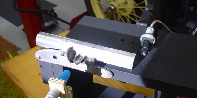
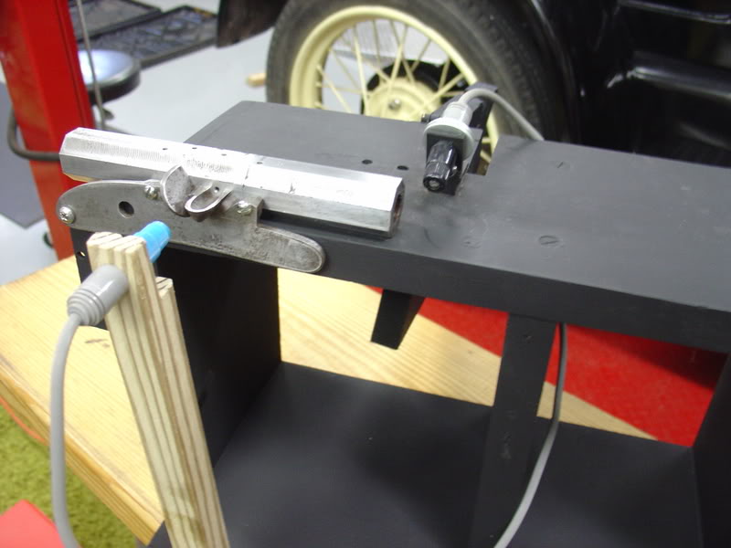
An L&R plate was chosen because the pan was attached. The plate was drilled and attached to a barrel stub with screws. The rear screw is attached to the barrel through a vertical slot in the lock plate. This allows for adjusting the height of the vent hole in relation to the plate.
At the rear of the plate a hole was drilled to provide a pivot point so that the barrel could be rotated to vertical for loading. The barrel is two inches long but is breeched by using a plug with an octagon shape, providing the same dimensions as the barrel.
The computer equipment used included a science interface designed for use in high school physics classes. The hardware was designed and built in the late 80’s. The computer is of similar vintage, but the combination allows measuring time intervals to the nearest 10,000th of a second.
This photo shows the fixture holding the barrel and the photo cells positioned at the pan and muzzle.
Pan Ignition Experiments
The experimentation has been broken into phases. The results of each section will be used in successive testing. The plan is to learn enough to control variables for our final experiment, which will be to the measure and evaluate of different vent locations. Each of the following parts is a link to the actual experiment. Methodologies used will be discussed as well as the experiment and the results.
Part 1 — Black Powder Ignition Characteristics
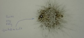
(Powder on sheets) This phase of testing was suggested to me by Mr. Bill Knight. Its purpose is to identify how the ignition travels across blackpowder exposed to the air as in a flint pan.
Part 2 — Initial Pan Experiments
(Card between barrel and pan) The card test was designed to determine the intensity of the flame at the vent. An index card was cut and pinched between the lock plate and the barrel. The pan was primed in three different positions.
Part 3 — Photography through the muzzle
In this phase I wanted to see if there was a visible difference in the amount of fire traveling through the vent. I used a digital camera to photograph the fire coming through the vent as seen from the muzzle. The camera is aimed to look directly into the barrel muzzle.
In this part we will examine the amount of priming powder used. Weighed amounts of powder will be timed. Plans call for .5 grains, .75 grains, and 1.0 grains of swiss Null B priming powder.
Part 5 — Timing Powder locations in Pan (Is it better to bank the powder away from the vent?)
The technique is to use photo cells to detect pan ignition and start the time. A second photo cell detects fire at the muzzle of the 2 inch barrel and stops the clock.. The methodology for this phase needed careful thought. Informal trials yielded some times that were out of predictable bounds. I suspect they were caused by an unknown variable, perhaps fouling.
Part 6 — Timing Vent locations (high, medium, low)
This final test will explore the ignition speed when the location of the vent hole is varied vertically. The test will start with the vent centered on the top of the pan. Other tests will be conducted with the vent as low in the pan as one could expect to find and with the vent located well above the pan center line.
 BlackPowderMag.com Flintlock Rifles and Black Powder Guns
